
Summary of Contents for ABonAir AB405
- Page 1 AB405 Installation and User Manual Wireless Broadcast System Confidential – Version 1.0 Copyright © 2018 ABonAir Ltd.
- Page 2 Before installing the system, please read this user manual carefully. It will help you to quickly and easily setup the system for flawless operation. This manual is intended for AB405 users, as well as for engineers who are integrating it with other production equipment.
- Page 3 AB405 Installation and User Manual Important Notice This manual contains proprietary information of ABonAir Ltd. No part of this publication may be reproduced in any form whatsoever without prior written approval of ABonAir Ltd. ABonAir and/or its agents and distributors make no claims or warranties concerning the fitness of the products or documentation for any purpose other than what is specifically described in this manual.
- Page 4 AB405 Installation and User Manual Limitation of Liability ABONAIR LTD. SHALL NOT BE LIABLE FOR ANY INCIDENTAL, INDIRECT, SPECIAL, CONSEQUENTIAL (EXCEPT FOR DAMAGES RELATING TO DEATH OR PERSONAL INJURY IN JURISDICTIONS WHERE SUCH DAMAGES MAY NOT BE DISCLAIMED AS A MATTER OF LAW),...
-
Page 5: Table Of Contents
Table of Contents AB405 Installation and User Manual Table of Contents Overview .................. 11 What is the AB405? ..............11 Package Contents ............... 12 1.2.1 Portable Receiver – Package Contents ......12 Product Orientation ..............13 AB405 Transmitter ............... 13 2.1.1... - Page 6 Figure 4: AB405 Receiver rear ............... 15 List of Tables Table 1: Portable Receiver – Package Contents ..........12 Table 2: AB405 Transmitter – Buttons, Connectors and LEDs ..... 14 Table 3: AB405 Receiver – Buttons, Connectors and LEDs ......15 Table 4: Troubleshooting ................21 Confidential –...
- Page 7 Terms and Abbreviations AB405 Installation and User Manual Terms and Abbreviations Acronym Description CVBS Color Video Blank Sync Light Emitting Diode MIMO Multiple In Multiple Out Power Supply Unit Radio Frequency RSSI Received Signal Strength Indication Receiver Transmitter Revision History...
- Page 8 Safety Symbols AB405 Installation and User Manual Safety Symbols The following safety symbols are used throughout this document. Familiarize yourself with the symbols and their meaning before installing or operating this instrument. WARNING! Denotes a hazard. It calls attention to a procedure that, if not correctly performed or adhered to, could result in injury or loss of life.
- Page 9 General Safety Warnings AB405 Installation and User Manual General Safety Warnings Always observe standard safety precautions during installation, operation and maintenance of this product. Only qualified and authorized personnel should carry out maintenance or repairs to the components of this system.
- Page 10 Getting Help AB405 Installation and User Manual Getting Help The system has undergone extensive testing prior to shipment. All its functions have been tested thoroughly. If you encounter any problems, please contact our support team for assistance in operation, setup or troubleshooting Support@AbonAir.com.
-
Page 11: Overview
This chapter describes the AB405 system and its package contents. What is the AB405? The ABonAir AB405 provides 33 msec latency figure cable to be upgraded to 7 msec, via a SW upgrade license. It has a 52+ db PSNR picture quality for broadcasting professionals. -
Page 12: Package Contents
Overview AB405 Installation and User Manual Package Contents The following lists the contents of the AB405 package in addition to the quantity and ABonAir serial number of each. 1.2.1 Portable Receiver – Package Contents Table 1: Portable Receiver – Package Contents... -
Page 13: Product Orientation
Product Orientation AB405 Installation and User Manual Product Orientation This chapter describes the buttons, Connectors and LEDs on each system component. AB405 Transmitter 2.1.1 Front Figure 1: AB405 Transmitter Front 2.1.2 Rear View Figure 2: AB405 Transmitter rear Confidential – Version 1.0... -
Page 14: Ab405 Receiver
Product Orientation AB405 Installation and User Manual Table 2: AB405 Transmitter – Buttons, Connectors and LEDs Buttons, Connectors and LEDs Antenna: RP-SMA male antenna ports. Power Input: Lemo 2-pin male connector. LED screen: Signal strength and other parameters Power Switch: Right position turns the transmitter on, indicated by a green LED. -
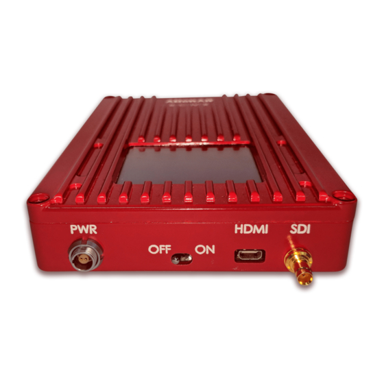
Page 15: Rear View
AB405 Installation and User Manual 2.2.2 Rear View Receiver rear view Figure 4: AB405 Receiver rear Table 3: AB405 Receiver – Buttons, Connectors and LEDs Buttons, Connectors and LEDs Antenna: SMA Male Antenna ports. Power Input: Lemo 2-pin male. LED Touch Screen... -
Page 16: Setup
Setup AB405 Installation and User Manual Setup This chapter describes how to install and connect the AB405 system. Transmitter 3.1.1 Connecting to the Camera The Transmitter has a Lemo 2 pin connector. To connect the camera: Attached the Transmitter to the camera Hot Shoe. -
Page 17: Receiver
Setup AB405 Installation and User Manual Receiver 3.2.1 Connecting the Monitor/Screen The receiver outputs one SDI or HDMI signals concurrently. Audio is provided embedded both in SDI or HDMI The receiver outputs one SDI and one HDMI signal simultaneously. To connect the Monitor: Connect the power supply to the Receiver Connect the Receiver outputs to the monitor. - Page 18 Setup AB405 Installation and User Manual Confidential – Version 1.0 Copyright © 2018 ABonAir Ltd.
-
Page 19: Operation
Troubleshooting AB405 Installation and User Manual Operation This chapter describes how to operate the AB405 system once it is installed. Wireless Video Connect the SDI or HDMI cables in both sides. Connect power cables in both sides. Turn on the Transmitter and Receiver. - Page 20 Troubleshooting AB405 Installation and User Manual Figure: RSSI bars Confidential – Version 1.0 Copyright © 2018 ABonAir Ltd.
-
Page 21: Troubleshooting
Troubleshooting AB405 Installation and User Manual Troubleshooting Table 4: Troubleshooting Symptom Solution Transmitter • Verify that the battery is charged. No Power • Check the transmitter using the Receiver power supply. Confirm that the transmitter is powered on. Confirm that the receiver is powered on. -
Page 22: B Recommended Antenna Setup
(as shown below). Tilting – point the antenna the right direction for a maximum signal strength Shaded Area – be aware of the shaded area under the antenna where signals are not received Confidential – Version 1.0 Copyright © 2018 ABonAir Ltd. - Page 23 The antenna is high on a mast but not in direct line of sight with the cameraman The result: signal is weak at the ground level, not reaching the cameraman and no transmission will be possible. Option 2: Confidential – Version 1.0 Copyright © 2018 ABonAir Ltd.
- Page 24 IMPORTANT: Make sure both antennas are pointing the same direction to create one strong signal. When 2 antennas are located both at the transmitting and receiving sites, they form a MIMO (multiple input multiple output) system. Confidential – Version 1.0 Copyright © 2018 ABonAir Ltd.
-
Page 25: C Connector Pin Descriptions
12 V DC Ant.1 and Ant.2 RP-SMA female antenna connector 5-6GHz. HD-SDI • HD-SD (High Definition Serial Digital) Interface DIN connector • Video HD-SDI output HDMI In/Out • Micro HDMI connector Confidential – Version 1.0 Copyright © 2018 ABonAir Ltd. -
Page 26: D Firmware Upgrade
Firmware Upgrade You can upgrade the newest firmware on your ABonAir system via USB. Please follow the steps below: Newest firmware on your ABonAir system Preparing to Update the Firmware: Make sure you have a USB flash drive (Disk-on key) formatted to... -
Page 27: Technical Specifications
5Ghz band - 4.9 - 5.875 Ghz (0.840 lb) RF Output Power: Preset: 50 mW to Environmen 300 mW tal: Operating Antenna Connector: N-type or fiber range: - (SM or MM) 10°C to +45°C Confidential – Version 1.0 Copyright © 2018 ABonAir Ltd. - Page 28 Frame Size: HD - 1920 x 1080, 1280 x Camera mount, SD - 720 x 576, 720 x 480 Codec: HIGH PROFILE H.264 CODEC GOP Size/Types: IP Frame Connector: SD/HD-SDI, Composite: 75 Ohm BNC connector Confidential – Version 1.0 Copyright © 2018 ABonAir Ltd.
-
Page 29: Health & Safety - Exposure To None Ionizing Radiation / Safe Working Distances
Health & Safety - Exposure to None Ionizing Radiation / Safe Working Distances ABonAir’s AB405 can be used without specific SAR testing, according to EN62311 and EN62479:2010 Annex B Harmonized Standard under the R&TTE directive. The various applicable electromagnetic field exposure limits contain different types of exposure parameters as a function of frequency and as a function of the type of limit reference level. - Page 30 =10 g in ICNIRP Guidelines [1] and IEEE Std C95.1-2005 [4], use Equations (E.2) to (E.5) in Equation (E.1): A= (− 0,4588 f 3 +4,407 f 2 − 6,112 f +2,497)/ 100 (Eq. E 6) Confidential – Version 1.0 Copyright © 2018 ABonAir Ltd.
- Page 31 (Eq. E 8) D = −0,03540 f 3 +0,5023 f 2 − 2,297 f +6,104 (Eq. E 9) In AB405 the conditions for these equations are as follow: Antenna BW: 1Ghz (20% at 5Ghz) Frequency of operation: 5- 6Ghz. Transmit power: 100-300mW.
-
Page 32: Gce Marking
CE Marking Confidential – Version 1.0 Copyright © 2018 ABonAir Ltd. - Page 33 Headquarters: ABonAir Ltd. 17 Atir Yeda St., Floor #4, Kfar Saba 4464313, ISRAEL Tel: +972.9.744.0055 support@abonair.com Confidential – Version 1.0 Copyright © 2018 ABonAir Ltd.
Need help?
Do you have a question about the AB405 and is the answer not in the manual?
Questions and answers