Advertisement
Quick Links
A Beijer Electronics Group Company
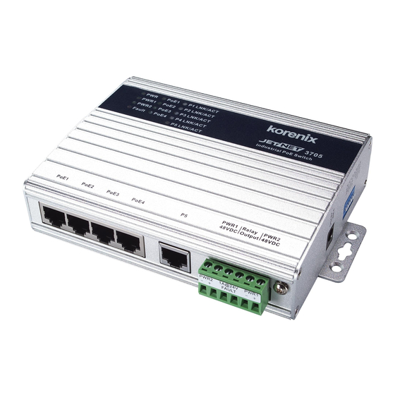
JetNet 3705 Series Industrial PoE Switch
Quick Installation Guide V1.3
Overview
JetNet 3705 / 3705f Series Industrial PoE Power Source Switch, conforming IEEE 802.3af
Power over Ethernet standard, supports 4 PoE 10/100Base-TX ports plus one extra
10/100Base-TX ( JetNet 3705 ) or 100Base-FX ( JetNet 3705f ) Ethernet port. Each PoE port
delivers power up to 15.4 watts in maximum. Using this Power Source switch can easily power
up PoE enabled devices, e.g. surveillance camera, wireless Access Point, VoIP phone set,
industrial sensor, security card reader via Ethernet cable.
Package Check List
LED for Power,
PoE Ethernet Link/ACT
JetNet PoE Switch
Mounting kit with footpad
Quick Installation Guide
PoE1-PoE4
Auto MDI/MDIX
Port5 Auto
10/100M Ethernet
MDI/MDIX10/100M
with PoE Output
Ethernet with
Installation
Mount the unit
Wall mount: Use the screws provided in the mounting kit and mount on the wall.
Din-Rail mount: Screw the DIN-Rail mounting pad to the ears and mount to DIN-Rail
track.
Grounding JetNet Switch
Connect the frame grounding of switch to the grounding
surface to ensure safety and prevent noise.
Wiring the Power Inputs
PWR1
1. Insert the positive and negative wires into the V+ and
V- contact on the terminal block connector.
2. Tighten the wire-clamp screws to prevent the DC wires
from being loosened.
Notes:
e suitable working voltage is 48VDC or -48VDC
Wiring the Relay Output
e relay output alarm contacts are in the middle of the
terminal block connector as shown in the gure below.
By inserting the wires and set the DIP switch of port
Relay Output Alarm Contacts
breaking or power input to "ON", relay output alarm will detect any power or port failures,
and form a Short circuit.
e alarm relay output is "Normal Open"
Communication Connection
1. Connecting the PoE Ethernet Ports: Connect one side of an Ethernet cable into the UTP
port of JetNet switch, while the other side is connected to the attached networking device. All
UTP ports support auto MDI/MDIX function.
10M Ethernet or Green for 100M Ethernet. Four Ethernet ports, from PoE 1 to PoE 4,
support PoE OUT. PoE port LED lit ON indicates that the RJ45 connector is successfully
connected to a IEEE 802.3af enabled Power Device.
2. Connecting the Fiber Ports (JetNet 3705f ): Connect the
ber port on your JetNet to another one located on another
Fiber Ethernet device, follow the
connection will cause ber ports not to work normally.
DIP Switch Settings for Alarm Relay Output
Pin No. #
Status Description
DIP Switch to
Enable Relay Output
ON
To enable PWR1 or PWR2 input failure alarm
PWR
(Pin 6)
Off
To disable Power inputs failure alarm
ON
To enable port break alarm at this port.
P1 to P5
(Pin1 ~5)
Off
To disable port break alarm at this port.
Din-Rail
Mounting Kit
48 VDC Power Jack
48 VDC Dual Power Inputs
And Relay Output
Support
5 Years Warranty
Each of Korenix's product line is designed, produced, and tested with high industrial
standard. Korenix warrants that the Product(s) shall be free from defects in materials and
workmanship for a period of ve (5) years from the date of delivery provided that the Product
was properly installed and used.
Earth Ground Screw
is warranty is voided if defects, malfunctions or failures of the warranted Product are
caused by damage resulting from force measure (such as oods, re, etc.), other external forces
such as power disturbances, over spec power input, or incorrect cabling; or the warranted
PWP2
Product is misused, abused, or operated, altered and repaired in an unauthorized or improper
way.
Attention! To avoid system damage caused by sparks, please DO NOT plug in power
connector when power is on.
e product is in compliance with Directive 2002/95/EC and 2011/65/EU of the European
Parliament and of the Council of 27 January 2003 on the restriction of the use of certain
hazardous substances in electrical and electronics equipment(RoHS Directives & RoHS 2.0)
.
Korenix Customer Service
KoreCARE is Korenix Technology's global service center, where our professional sta s are
ready to solve your problems at any time Korenix global service center's e-mail is
KoreCARE@korenix.com.
e LNK / ACT LED will turn Yellow for
For more information and documents download please visit our website:
http://www.korenix.com/downloads.htm
RX
RX
gure below. Wrong
TX
TX
Cable Wiring(SC to SC)
TX A
RX B
RX A
TX B
Alarm Switch
1
2
3 4
5
6
1 2
3
4
5
Advertisement

Related Manuals for Korenix JetNet 3705 Series


Summary of Contents for Korenix JetNet 3705 Series
- Page 1 1. Connecting the PoE Ethernet Ports: Connect one side of an Ethernet cable into the UTP ready to solve your problems at any time Korenix global service center's e-mail is port of JetNet switch, while the other side is connected to the attached networking device. All...
- Page 2 官网: www.korenix.com.cn ”V-“接口。 2. 拧紧线夹防止DC电源线脱落。 备注: 适用工作电压是48VDC 或者-48VDC 连接报警系统 继电器报警输出触点在接线端子连接槽的中部,如 图所示B将线接入,并将交换机上对应断电断线报警 的DIP开关置”ON”,继电器报警系统一旦发现断电 Korenix Technology Co., Ltd. Patent No. (Taiwan): 断线情况,自动建立一个闭合的电源回路,触发报 Granted Invention: I 313547 Relay Output Alarm Contacts (A Beijer Electronics Group Company) Granted Invention: I 321415 警,而正常情况下则是一个开路。 Granted Invention: I 344766 通讯线路的连接...
Need help?
Do you have a question about the JetNet 3705 Series and is the answer not in the manual?
Questions and answers