Advertisement
Quick Links
Advertisement

Subscribe to Our Youtube Channel
Related Manuals for Melink Intelli-Hood Controls

Summary of Contents for Melink Intelli-Hood Controls
- Page 1 REFERENCE GUIDE Melink Corporation (513) 527-7020 www.melinkcorp.com Rev. 1.6...
- Page 3 Table of Contents Section 1: Intelli-Hood Operation and Simplissimo Settings Section 2: Troubleshooting/ Component Compatibility Section 3: Drive Connections Section 4: Drive Programming Section 5: Helpful Phone Numbers and Contact Information...
- Page 5 Section 1: Intelli-Hood Operation and Simplissimo Settings...
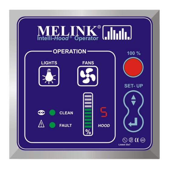
- Page 7 Operation/Service Specifications for Melink Intelli-Hood Operator KEYPAD OPERATION • LIGHTS Button - Turns hood lights on and off if I/O board output is tied into the hood light circuit. Also turns APU blowers on and off. • FANS Button - Turns the fans on and off. Also turns APU blowers on and off.
- Page 8 Operation/Service Specifications for Melink Intelli-Hood Operator • To reset average VFD speeds: Must be in setup mode. Must be at the flashing '0'. Press and hold the ENTER key for 10 seconds. A 'r' will show on the 7-segment display.
- Page 9 Operation/Service Specifications for Melink Intelli-Hood Operator Simplissimo Settings Hood Settings Exhaust Temp Span - This sets up the temperature span for modulating VFD speed between its set minimum and maximum based on temperature. The span has a low value of 75...
- Page 10 Operation/Service Specifications for Melink Intelli-Hood Operator System Settings Auxiliary VFD Output - This sets up how the signal is determined for the auxiliary VFD output. • No - No auxiliary output • Average - send the average of the used VFDs on board.
- Page 11 Operation/Service Specifications for Melink Intelli-Hood Operator selected with the processor running. It will be turned off if all of the exhaust temperatures fall below 85 F or after the hang time on the optics has expired. The motor starter can also...
- Page 12 Operation/Service Specifications for Melink Intelli-Hood Operator Kitchen Temp Exhaust Temp Bar Graph VFD Speed Outside Temp (o) Optics Align. V3.7-V4.4/V4.5 91-100% 146+/150+ 2.71+V 81-90% 141-145/140-149 91-95 81-90 2.41V-2.7V 71-80% 136-140/130-139 86-90 71-80 2.11V-2.4V 61-70% 131-135/120-129 81-85 61-70 1.81V-2.1V 51-60% 126-130/110-119...
- Page 15 Section 2: Troubleshooting And Component Compatibility...
- Page 17 MELINK Intelli- Hood Operator TROUBLESHOOTING @ MELINK KEYPAD PROBLEM: ITEMS TO CHECK: a. Determine which hood is not working - refer to digit next to bar graph. KEYPAD b. Determine fan speed by counting # of bars illuminated on bar graph, if any.
- Page 18 MELINK VOLTS AMPS HERTZ Intelli- Hood Operator PROGRAM FAULT TROUBLESHOOTING @ DRIVE KEYPAD PROBLEM: ITEMS TO CHECK: a. Check AC power input to drive for low voltage or line power interruption. Under Voltage Under Voltage a. Check AC power input to drive for high line voltage . Assure deceleration time is set at 60 sec.
- Page 19 DATA PROBLEM: ITEMS TO CHECK: OC 1, a. Remove run command to Drive by turning off fan switch on Melink Keypad. Green light on Drive that says RUN should go out. Press PRG/RESET over current during on drive to remove fault. Or, turn off breaker to drive and then back acceleration on again after 30 sec.
- Page 20 Operation/Service Specifications for Melink Intelli-Hood Operator Advanced Troubleshooting This section will deal with phenomena that are not mentioned in the standard troubleshooting guide. The following actions take a more subjective approach to the problems. General Procedure For Isolating Bad Components Temperature Sensors •...
- Page 21 Operation/Service Specifications for Melink Intelli-Hood Operator Change out optic “Y” cable at IOP. Preferably switch with a working optic channel in order to ensure a good “Y” is being used. If a “Y” from a working optic channel is not being used, try a second “Y”...
- Page 23 VFD Display Codes AC Tech Drives Display Fault Description/Possible Causes High Temperature Fault Ambient temperature too high; cooling fan failed Blank or corrupted EPM installed. Perform factory reset Control Fault (Parameter 48) or change EPM. Incompatible EPM installed. Perform factory reset Incompatibility Fault (Parameter 48) or change EPM.
- Page 24 Operation/Service Specifications for Melink Intelli-Hood Operator Output Wire Lengths Due to possibility for interference, the distance between the drive output and the motor being controlled must be less than a specified distance. If the distances specified below must be exceeded, an output filter must be installed on the application.
- Page 25 Operation/Service Specifications for Melink Intelli-Hood Operator Optic Gain Settings/Compatibility Gain Setting Rev A Emitter & Rev C Receiver Rev B Emitter & Rev D Receiver 5'-11' 4'-8' Middle 11'-25' 8'-18' Bottom 25'-50' 18'-40' Note: Optics are not cross-compatible (i.e. Rev A Emitter will not work with Rev D Receiver)
- Page 27 Section 3: Drive Connections...
- Page 29 A-B PowerFlex 4 Drive Terminal Connections VOLTS AMPS HERTZ PROGRAM FAULT 01 02 R1 R2 Color Terminal Pin Purpose Notes: 4-20mA Speed Ref. - Move SNK/SRC switch to SNK Black 0-10 VDC Feedback - Set AutoCal dipswitches to 0-10VDC White Run Command Blue Bypass Command...
- Page 30 GE Micro$averII Drive Terminal Connections GE/FUJI 60.00 MICRO-SAVER II RESET FUNC STOP DATA 30B Y1 FMA PLC BX RST C1 13 12 11 30C FMP X1 X2 X3 X4 REV FWD THR L1 L2 L3 Color Terminal Pin Purpose 4-20 mA Black 0-10 VDC Out White...
- Page 31 P11 Terminal Connections HIGH VOLTAGE LEGEND TERMINAL FUNCTION 3Phase Input from breaker panel 3Phase Output to fan motor LOW VOLTAGE CABLE LEGEND WIRE FUNCTION COLOR TERM White Run command Orange Run common Blue Bypass command 4-20mA speed referance Remove Jumper to connect external trip Yellow Speed referance common Black...
- Page 32 AC Tech Terminal Connections AC Tech 6 11 12 2 14 13A 13B 13C 15 25 2 30 31 TXA TXB FUNCTION SIGNAL Terminal PIN # RECPTACLE Speed Reference to VFD 4-20 ma Frequency Meter from VFD 0-10 vdc Black Start/Stop Command White Full Speed Bypass Command...
- Page 33 8-Pin (VFD) Cables Older Receptacle/ Terminal Purpose Cables Newer Cables Black 4-20 mA Black 0-10 VDC Out White White Run Command Green Blue Bypass Command Brown Yellow Signal Common Blue Orange FWD/Bypass Common Orange Brown 0-10 VDC In Bare Green Male End View 4-Pin Cables Color...
- Page 34 Temperature “Y” Connector Note: Legs on temperature “Y”s are approximately 10” long. APU “Y” Connector Note: Legs on APU “Y”s are approximately 8” long.
- Page 35 Optic “Y” Connector Emitter Leg (~8” Long) Receiver Leg (~9” Long) Communication Cable...
- Page 36 GE Drive Master/Slave Terminal Connections Master Slave Terminal Purpose Terminal Purpose 0-10 VDC Input => 0-10 VDC Input Signal Common => Signal Common Bypass Signal => Bypass Signal Common => Common Note: Need to jumper in run command on slave drive (on GE drives terminal FWD to CM) Drive Remote Run Command (Relay Connections) GE/FUJI 60.00...
- Page 37 VFD Fire Suppression Interlock This configuration will shut down the supply fan and send the exhaust fan to full speed when fire suppression system is tripped. EXHAUST FAN VFD SUPPLY FAN VFD GE/FUJI GE/FUJI MICRO-SAVER II MICRO-SAVER II RESET RESET FUNC FUNC STOP...
- Page 38 3-10...
- Page 39 3-11...
- Page 40 Input/Output Board AUXILIARY INPUTS 24 vdc Com Relay Coil Sink Aux Out 0-10vdc Aux Out Com Aux Out 4-20 ma Shield Aux In Com Aux In 4-20 ma Relay Input Dry Relay Input Dry Sup Temp Sens Sup Temp Sens Shield Kitchen Temp Kitchen Temp...
- Page 41 Section 4: Drive Programming...
- Page 43 Allen Bradley - PowerFlex 4 Series VFD Program Function Code Settings Intelli-Hood Application FUNC # SETTING DESCRIPTION d001 Read Only OUTPUT FREQUENCY d002 Read Only COMMANDED FREQUENCY d003 Read Only OUTPUT CURRENT d004 Read Only OUTPUT VOLTAGE d007-d009 Read Only FAULT CODES (Displays history of past three fault codes, with d007 being the most recent) P031 VOLTS MOTOR NP VOLTS - Set at motor rated volts (208, 220, 230, 380, 400, 460 ,480)
- Page 44 BIAS FREQUENCY (0 = no offset) GAIN FOR FREQUENCY SIGNAL (in Percent of Maximum Frequency) 0-60 HIGH LIMITER (Set to Air Balance Speed in Hz) [60 is Melink default] LOW LIMITER (in Hz) DATA INITIALIZATION (0 = Inactive, 1 = Reset to Factory Default Values)
- Page 45 ELECTRONIC THERMAL OVERLOAD BRAKING (1 = Active for Built-In Resistor) RESTART AFTER MOMENTARY POWER FAILURE (3=Restart Active with Ride-Through) 0-60 FREQUENCY HIGH LIMIT (Set to Air Balance Speed in Hz) [60 is Melink Default] FREQUENCY LOW LIMIT (in Hz) FREQUENCY GAIN (in Percent)
- Page 46 AC Tech SCF Series VFD Program Function Code Settings Intelli-Hood Application FUNC # SETTING DESCRIPTION 01 or 02 LINE VOLTAGE (01 = High , 02 = Low) ( Refer to nameplate voltage ratings, high and low) CARRIER FREQUENCY (02 = 6 kHz) START METHOD (02 = Start on Power-up) STOP METHOD (03 = Ramp) STANDARD SPEED SOURCE (04 = 4-20 mA, 03 = 0-10 VDC, 02 = Preset #1, 01 = Keypad)
- Page 47 TECO FM7500 Program Function Code Settings Intelli-Hood Application FUNC # SETTING DESCRIPTION Output Frequency Run Scale Run Units 0 Hz Min Hz 60 Hz Max Hz Ramp 5 sec Acceleration Time 60 sec Deceleration Time .5 sec S Time Flux Plus Hi Speed Flux Slip Compensation DC Hold...
- Page 48 RESTART AFTER MOMENTARY POWER FAILURE (3 = Restart Active at Starting Frequency) 0-60 FREQUENCY HIGH LIMIT (Set to Air Balance Speed in Hz) [60 is Melink Default] FREQUENCY LOW LIMIT (in Hz) FREQUENCY GAIN (0 = For 0 to +10VDC)
- Page 49 JUMP FREQUENCY 2 JUMP FREQUENCY 3 0-100 HIGH LIMITER (Set to Air Balance Speed as a % of Max. Freq) [100 is Melink default] LOW LIMITER (% of Max. Frequency) BIAS FREQUENCY THR TERMINAL FUNCTION (0 = THR Terminal to be used for External Trip) (Jumper THR-CM)
- Page 50 GE/Fuji AF-300 Micro-Saver II Series VFD Program Function Code Settings Electronic Motor Starter Application FUNC # SETTING DESCRIPTION DATA PROTECTION (0 = Allows Data Changing, 1 = Lock Settings) FREQUENCY COMMAND (0 = Frequency Setting with Keypad Arrow Keys) OPERATION COMMAND (2 = Fwd Run Command Through Terminal Input, STOP key inactive) MAXIMUM FREQUENCY (in Hz) (Set to 60 for USA, 50 for EU) BASE FREQUENCY (in Hz) (Set to 60 for USA, 50 for EU) VOLTS...
- Page 51 ELECTRONIC THERMAL OVERLOAD OPERATION (1= Active for General-Purpose Motor) 20 - 135% ELECTRONIC THERMAL OVERLOAD LEVEL (% = (Motor FLA)/(VFD Rated A)x100) (Calculate Motor FLA as a Percentage of VFD FLA) [100 is Melink Default] ELECTRONIC THERMAL OVERLOAD TIME (in seconds)
- Page 52 GE/Fuji AF-300 C11 Series VFD Program Function Code Settings Electronic Motor Starter Application FUNC # SETTING DESCRIPTION DATA PROTECTION (0 = Allows Data Changing, 1 = Lock Settings) FREQUENCY COMMAND (0 = Frequency Setting with Keypad Arrow Keys) OPERATION COMMAND (2= Fwd Run Command Through Terminal Input, STOP key inactive) MAXIMUM FREQUENCY (in Hz) (Set to 60 for USA, 50 for EU) BASE FREQUENCY (in Hz) (Set to 60 for USA, 50 for EU) ACCELERATION TIME (in seconds)
- Page 53 ELECTRONIC THERMAL OVERLOAD RELAY OPERATION (1= Active for 4-Pole Motor) 30 - 100% ELECTRONIC THERMAL OVERLOAD RELAY LEVEL (% = (Motor FLA)/(VFD Rated A)x100) (Calculate Motor FLA as a Percentage of VFD FLA) [100 is Melink Default] RESTART AFTER MOMENTARY POWER FAILURE (1=Restart Active)
- Page 54 ELECTRONIC THERMAL OVERLOAD LEVEL (Set to Motor Rated FLA) DC BRAKE (0 = Inactive) 0-60 MULTI STEP SPEED 1 (Set to Air Balance Speed in Hz) [60 is Melink default] (Jumper X1-CM) S-CURVE ACC/DEC (1 = Weak S-Curve) FAULT MEMORY...
- Page 55 X2 TERMINAL FUNCTION (1 = Multi-Step Frequency set in C06) (Jumper X2-CM) X3 TERMINAL FUNCTION (4 = External Alarm Trip THR) (Jumper X3-CM) MULTI-STEP FREQUENCY 1 (in Hz) 0-60 MULTI-STEP FREQUENCY 2 (Set to Air Balance Speed in Hz) [60 is Melink Default] MOTOR CHARACTERISTICS OPERATION TIME ACCUMULATION TRIP HISTORY...
- Page 56 MULTI SPEED SETTING 1 (in Hz) 0-60 MULTI SPEED SETTING 2 (Set to Air Balance Speed in Hz) [60 is Melink Default] MULTI SPEED SETTING 3 (in Hz) METER ADJUSTMENT SCALE (0 = 6.5 v at Full Scale, 99 = 10.3 v at Full Scale) METER OUPUT SELECTION (0 = Output Frequency at FM Terminal) Prog_C9.123...
- Page 57 Default Overload Settings M$: Function F16 P11: Function F11 Note: Actual motor FLA’s may vary. Settings below are for general reference. 115 Volt Protect 200 Volt Protect 230 Volt Protect 460 Volt Protect 575 Volt Protect +10 % No OLs +10 % No OLs +10 %...
- Page 59 Section 5: Helpful Phone Numbers and Contact Information...
- Page 61 Helpful Phone Numbers: Phone Website Technical Support AC Tech 1-800-217-9100 www.actechdrives.com General Electric 1-800-533-5885 www.ge.com Melink Corporation 1-877-477-4190 www.melinkcorp.com Car Rental Alamo 1-800-327-9633 www.goalamo.com Avis 1-800-331-1212 www.avis.com Budget 1-800-527-0700 www.budget.com Dollar 1-800-800-4000 www.dollar.com Enterprise 1-800-736-2227 www.enterprise.com Hertz 1-800-654-3131 www.hertz.com National 1-800-227-7368 www.nationalcar.com...
- Page 62 Melink Corporation 5508 Fair Lane Cincinnati, Ohio 45227 Phone: (513)527-7020 Fax: (513)527-7023...
Need help?
Do you have a question about the Intelli-Hood Controls and is the answer not in the manual?
Questions and answers