Table of Contents
Advertisement
Available languages
Available languages
Quick Links
Advertisement
Table of Contents

Related Manuals for INTERSPIRO Spiroguide II


Summary of Contents for INTERSPIRO Spiroguide II
- Page 1 ENGLISH SWEDISH SPIROGUIDE II User Manual - Handhavande Manual 31268F91...
-
Page 2: Table Of Contents
TABLE OF CONTENTS - INNEHÅLLSFÖRTECKNING USER MANUAL - ENGLISH SAFETY NOTICE ............CYLINDER MOUNTING ..........INSTALLING / REMOVING HUD ........ADJUSTING SIZE ............DONNING..............START-UP TEST ............DURING USE ............. CYLINDER PRESSURE WARNING ........ AUTOMATIC DISTRESS SIGNAL UNIT(ADSU)- (OPTIONAL) 10 REMOVING THE APPARATUS ........CLEANING AND DISINFECTING ........ - Page 5 16:b 16:a – –...
-
Page 6: Safety Notice
Individuals with beards or large sideburns may not obtain an adequate seal. The apparatus must be maintained, serviced and tested as described in this user manual, Interspiro service manuals and Interspiro test instructions. INTERSPIRO IS NOT RESPONSIBLE FOR... - Page 7 Changes to this document - necessitated by typographical errors, inaccuracies of current information or improvements and changes of equipment - may be made at any time without prior notice. Always refer to www.interspiro.com for product updates, document updates and service bulletins. Exposure to extreme conditions, may require different procedures rather than those described in this manual.
-
Page 8: Cylinder Mounting
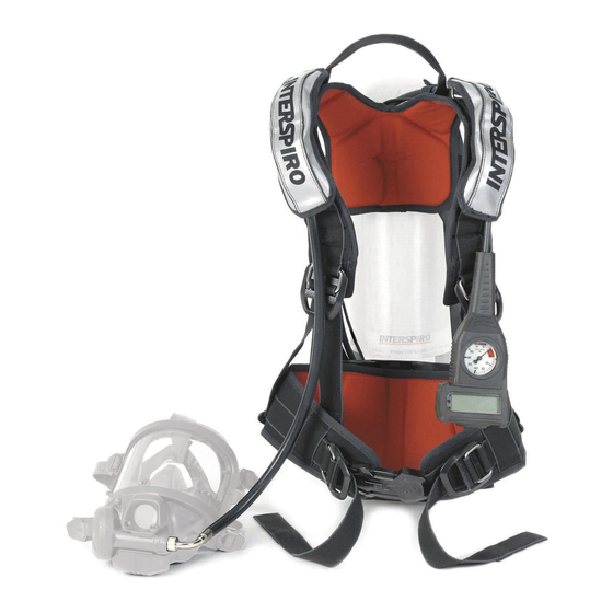
CYLINDER MOUNTING SINGLE CYLINDER Check that the cylinder strap buckle is positioned with the buckle as close to the backplate as possible. Place the cylinder on the backplate. [Fig. 1] Check the connection O-ring and screw the cylinder valve hand tight to the cylinder connection of the manifold block. -
Page 9: Installing / Removing Hud
CYLINDER PACK Mounting Place the cylinder pack on a flat surface with the cylinder valve towards you. Check the connection O-ring and screw the cylinder valve hand-tight to the cylinder connection of the manifold block. [Fig. 7] NOTE! FOR CYLINDER QUICK COUPLING SEE SECTION CYLINDER QUICK COUPLING OPTION. Fit the holes of the cylinder bracket onto the guide washers and push the backplate away from you until the harness clicks in position [Fig. -
Page 10: Adjusting Size
ADJUSTING SIZE NOTE! WHEN STANDING STRAIGHT WITH THE BREATHING APPARATUS DONNED THE MAJORITY OF THE WEIGHT SHALL BE CARRIED ON THE HIPS AND NOT THE SHOULDERS. To adjust the height of the hip belt, push the red buttons under the hip belt together and slide the complete hip belt up or down to the correct size. - Page 11 Only conducted if Full Test is performed ATTENTION! ALWAYS FOLLOW YOUR ORGANIZATION’S POLICY TO DETERMINE WHETHER AN OPERATION MAY BE PERFORMED AFTER THE OCCURRENCE OF FAILURE INDICATION(S). PERFORMING THE “SHORT TEST” Open the cylinder valve fully. The display reads according to the figure below. INTERSPIRO...
- Page 12 See the section titled “Test Results”. PERFORMING THE “FULL TEST” Open the cylinder valve fully. The display reads according to the figure below. INTERSPIRO Check the sound. CHECK SOUND Press the backlight button (section 7, Fig. 7-A) during the three seconds that the display reads according to the figure below.
- Page 13 LEAKAGE TEST For Tally key activated SpiroGuide II the display will read according to the figure below. If the tally is not inserted from the start the display will first read “INSERT TALLY“ and then “REMOVE TALLY“ when the tally has been inserted.
- Page 14 Press the red button when the display reads according to the figure below. PRESS RED Panic alarm sound is tested. CHECK SOUND For SpiroGuide II with SpiroLink activated, press red and black buttons to test the evacuation alarm when the display reads according to the figure below. HOLD BLACK &...
-
Page 15: During Use
See the section titled “Test Results” above. The display will toggle between the two figures below. To shut down the SpiroGuide II press the backlight button. To go into Run mode, switch off the positive pressure of the breathing valve and open the cylinder valve... - Page 16 If only one value is shown, there is no toggle function and the backlight button works as a backlight only. Pressing the backlight button repeatedly toggles between values. When the backlight is switched off after four seconds the display will always show the default value. During use, the remaining air time is calculated based on the previous air consumption.
- Page 17 HEADS-UP DISPLAY (HUD) - OPTIONAL A light sensor automatically adjusts the brightness of the LEDs according to the ambient light conditions. This may take up to 10 seconds. CYLINDER PRESSURE INDICATION 100% GREEN, YELLOW, YELLOW, RED IS LIT YELLOW, YELLOW, RED IS LIT LOW AIR YELLOW, RED IS LIT LOW AIR...
- Page 18 NOTE: ONLY ONE USER CAN CHECK THE HUD LINK AT THE TIME. IF SEVERAL USERS TEST THE HUD LINK AT ONCE IT WILL BE IMPOSSILBLE TO TELL IF THE HUD IS LINKED TO THE CORRECT SPIROGUIDE II OR NOT. BREATHING APPARATUS COMPUTER (BAC) The BAC is measuring the pressure and supplying the information to the Digital Display and HUD.
-
Page 19: Cylinder Pressure Warning
If fitted and function activated, the HUD flashes (the active pressure indication LEDs) for 10 seconds. NOTE: WHEN DEPRESSURIZING THE UNIT RAPIDLY AFTER USE, THE SPIROGUIDE II SOMETIMES SHUTS DOWN WITHOUT ANY LOW AIR WARNING OR TURN BACK SIGNAL. REDUCED VOLUME (OPTIONAL) To reduce volume when for example working in gas tight suits, pressurize the SpiroGuide II and press the panic button when the display reads as shown below. -
Page 20: Automatic Distress Signal Unit(Adsu)- (Optional)
AUTOMATIC DISTRESS SIGNAL UNIT(ADSU)- (OPTIONAL) ACTIVATION/DEACTIVATION AND ALARM RE-SET VERSION WITH TALLY KEY (ADSU) Remove the Tally by pulling it straight out from the display unit to activate the ADSU. Once in alarm mode the ADSU can only be re-set by inserting the Tally. VERSION WITHOUT TALLY KEY (PASS) –... -
Page 21: Cleaning And Disinfecting
Check that the pressure do not drop. Decrease the cylinder pressure slowly and check that the whistle starts sounding at 55 ±5 bar. Service and testing shall be performed according to Service and testing schedule 97307. Visit www.interspiro.com for latest revision. -
Page 22: Batteries
BATTERIES Always use the Duracell MN2400 and Energizer E92 AAA alkaline batteries. Interspiro assumes no liability for mechanical, electrical or any other type of battery failure. Do not mix battery manufacturers or old with new batteries. HUD AND BAC BATTERY WARNINGS During use, battery warning is given as described in section 6. -
Page 23: Storage And Transport
STORAGE AND TRANSPORT Store in a cool, dry and dust-free environment. Protect rubber parts from direct sunlight, UV radiation and direct heat. When the regulator unit is not connected, the cylinder valve should always have a protective plug. The unit should be stored with the face mask/breathing valve in the position for activated positive pressure. -
Page 24: Markings
Connect the quick coupling of the SCBA to the airline supply hose. The higher pressure in the supply hose should shut off the supply from the SCBA. After two minutes, read the pressure displayed on the pressure gauge again. During the elapsed time, there should be no measurable drop in pressure on the gauge. -
Page 25: Säkerhetsanvisningar
Interspiro servicehandböcker och Interspiro testanvisningar. INTERSPIRO ANSVARAR INTE FÖR UNDERHÅLL OCH REPARATIONER SOM UTFÖRTS AV PART SOM INTE INNEHAR GILTIGT INTERSPIRO SERVICECERTIFIKAT KOMBINATIONER AV PRODUKTER, OM DESSA INTE SÄLJS AV INTERSPIRO FÖRÄNDRINGAR ELLER ANPASSNINGAR AV PRODUKTEN UTFÖRDA AV TREDJE PART... - Page 26 Besök vår webbsida www. interspiro.com för produkt- och dokumentuppdateringar och för servicemeddelanden. Exponering för extrema förhållanden kan kräva andra åtgärder än de som nämns i denna handbok.
-
Page 27: Montering Av Flaska
MONTERING AV FLASKA ENKELFLASKA Kontrollera att flaskbandets spänne är placerat så nära ryggplattan som möjligt. Placera flaskan på ryggplattan. [Bild 1] Kontrollera den tätande O-ringen och skruva fast flaskventilen för hand i samlingsstycket. [Bild 1] OBS! FÖR SNABBKOPPLING SE AVSNITT FLASKSNABBKOPPLINGSTILLVAL. Dra åt flaskbandet runt flaskan och haka fast det med spännet. -
Page 28: Ansluta / Ta Loss Hud
FLASKPAKET Montering Placera flaskpaketet på en plan yta med flaskventilen vänd mot dig. Kontrollera att den tätande O-ringen sitter på plats och skruva fast flaskventilen för hand i samlingsstycket. [Bild 7] OBS! FÖR FLASKSNABBKOPPLING SE AVSNITT FLASKSNABBKOPPLINGSTILLVAL.. Passa in fästskenans hål på dubbarna och skjut ryggplattan bort från dig tills bärstället klickar i läge. -
Page 29: Justera Storleken
JUSTERA STORLEKEN OBS! NÄR MAN STÅR UPPRÄTT MED ANDNINGSAPPARATEN PÅTAGEN SKA MERPARTEN AV VIKTEN BÄRAS PÅ HÖFTERNA OCH INTE PÅ AXLARNA. Tryck ihop de röda knapparna under höftbältet för att justera höftbältet i höjdled. Skjut höftbältet uppåt eller nedåt till korrekt storlek. [Bild 12] Bärstället kan justeras i fyra olika storlekar. - Page 30 Byt batteriet omgående efter utfört uppdrag eller om möjligt innan uppdraget fortsätts. Utförs enbart i Fullt test. OBS! FÖLJ ALLTID DIN ORGANISATIONS POLICY AVSEENDE FORTSATT ARBETE EFTER FÖREKOMST AV FELINDIKERING(AR). UTFÖRA “SNABBTEST” Öppna flaskventilen helt. Displayen visar enligt nedan. INTERSPIRO...
- Page 31 Displayen stannar nu och visar resultatet av testet tills svarta knappen trycks in. Se avsnittet ”Testresultat”. UTFÖRA “FULLSTÄNDIGT TEST” (FULLT TEST ) Öppna flaskventilen helt. Displayen visar enligt nedan. INTERSPIRO Kontrollera ljudet. KOLLA LJUD Tryck in svarta knappen (avsnitt 7, Bild 7-A) under de tre sekunder som displayen ser ut som i figuren nedan.
- Page 32 Displayen skiftar till att visa enligt nedan. LÄCKAGE TEST Vid användning av spärrnyckel aktivering på SpiroGuide II kommer displayen att visa enligt nedan. Om spärrnyckeln inte är inkopplad från start kommer displayen först visa “SÄTT I NYCKEL“ och därefter “TA BORT NYCKET“ när spärrnyckeln har blivit inkopplad.
- Page 33 Tryck på den röda knappen när displayenheten visar enligt nedan. TRYCK RÖD Kontrollera ljudet. KOLLA LJUD För SpiroGuide II med SpiroLink aktiverad, tryck röd och svart knapp för att testa evakueringslarmet när displayen visar enligt nedan. HÅLL SVART & TRYCK RÖD Evakueringslarmet testas när displayen visar enligt nedan.
-
Page 34: Under Användning
Displayen stannar nu och visar resultatet av testet tills ljusknappen trycks in. Se avsnittet ”Testresultat” ovan. Displayen växlar mellan två lägen. För att stänga av SpiroGuide II tryck på den svarta knappen. För att gå till driftläge, stäng av säkerhetstrycket på... - Page 35 Beroende på inställning kan displayen visa ett, två, tre eller alla fyra av dessa värden. Dessutom kan valfritt värde av dessa fyra visas som standard eller ges andra, tredje eller fjärde prioritet. När du trycker på den svarta knappen (Bild 7-A) aktiveras displayens bakgrunds- belysning i fyra sekunder.
- Page 36 HEADS-UP DISPLAY (HUD) - TILLVAL En ljussensor justerar automatiskt ljusdiodernas styrka efter det omgivande ljuset. Detta kan ta upp till 10 sekunder. FLASKTRYCKSINDIKERING 100% GRÖNT, GULT, GULT, RÖTT ÄR TÄNT GULT, GULT, RÖTT ÄR TÄNT LOW AIR GULT, RÖTT ÄR TÄNT LOW AIR RÖTT ÄR TÄNT STANDARDINSTÄLLNINGEN FÖR ”LÅGT LUFTTRYCK”...
- Page 37 Håll den svarta knappen nedtryckt tills displayen stängs av. KONTROLL AV FÖRBINDELSE MELLAN HUD OCH SPIROGUIDE II Kontroll kan ske för att säkerställa att HUD:en är förbunden med rätt SpiroGuide II. För att göra denna kontroll, håll den svarta knappen nedtryckt i två sekunder, släpp knappen en sekund och håll den därefter nedtryckt i ytterligare två...
-
Page 38: Flasktrycksvarningar
LÅGT TRYCK OCH ÅTERTÅG. SÄNKA VOLYMEN (TILLVAL) För att sänka volymen, exempelvis vid arbete i helkapslad kemdräkt, trycksätt SpiroGuide II och tryck på den röda knappen när displayen visar som nedan. LÅGT LJUD TRYCK RÖD Tryck på den svarta knappen när displayen visar som nedan. -
Page 39: Rörelselarm (Adsu/Pass)- Tillval
Därefter visar displayen enligt nedan. BEKRÄFTAD RÖRELSELARM (ADSU/PASS)- TILLVAL AKTIVERING/AVAKTIVERING OCH ALARMÅTERSTÄLLNING VERSION MED SPÄRRNYCKEL (ADSU) Ta ur säkerhetsnyckeln genom att dra den rakt ut ur displayenheten, detta aktiverar ADSU:n. När ADSU är i alarmfunktion kan den enbart återställas genom att säkerhetsnyckeln sätts tillbaka i displayenheten VERSION UTAN SPÄRRNYCKEL (PASS) –... -
Page 40: Ta Av Apparaten
TA AV APPARATEN Stäng av säkerhetstrycket. Öppna spännena för att lossa bandstället över huvudet, lossa bandstället och ta av ansiktsmasken. Stäng flaskventilen. OBS: FÖR ATT UNDVIKA OAVSIKTLIG STÄNGNING AV FLASKVENTILEN MÅSTE RATTEN TRYCKAS IN INNAN DEN VRIDS. Om tillämpligt, lossa bröstspännet. Lossa midjeremmens spänne och axelremmarna. -
Page 41: Service Och Test
Utför regelbunden service i enlighet med service- och testschemat 97307. Besök www. interspiro.com för den senaste versionen. BATTERIER Använd alltid Duracell MN2400 och Energizer E92 AAA alkaline batterier. Interspiro åtar sig inget ansvar för mekaniska, elektriska eller andra typer av batterifel. Blanda inte batterifabrikat eller gamla med nya batterier. -
Page 42: 14 Förvaring
Ta bort de två skruvarna från batteriluckan med en kryssmejsel (philips). [Bild 16:a] Ta bort batteriluckan. Därefter, ta ur batterifacket genom att lyfta i handtaget. [Bild 16:b] Sätt i tre nya AAA-batterier som markeringarna på insidan av batterifacket visar. [Bild 17] Sätt samman batterifacket och skjut in det i BAC:en. -
Page 43: Användning Med Luftförsörjningssystem
När luft tas från apparaten (punkterna 1 - 4 ovan) ökar konsumtionen av luft, och apparatens aktionstid minskar. En speciell kopplingshona med en backventilöppnare måste användas när luft tas från apparaten (punkterna 1 - 4 ovan). Denna anordning öppnar backventilen i kopplingshanen på... -
Page 44: 17 Märkning
MÄRKNINGAR Tillverkare Modellbeteckning Serienummer Europeisk norm och klassificering Tillverkningsår PRODUKTEN FÅR INTE SLÄNGAS I HUSHÅLLSSOPORNA Symbolen överkryssad soptunna på denna produkt, dess förpackning och instruktioner betyder att produkten tillverkades efter 13/8/05 och lyder under Europa direktiven 2002/96/EC, utfärdade 27/1/03, för korrekt hantering av elektriskt och elektroniskt avfall (WEEE).
Need help?
Do you have a question about the Spiroguide II and is the answer not in the manual?
Questions and answers