Crown Boiler BWF Series Installation Instructions Manual
Gas-fired induced draft hot water boiler
Hide thumbs
Also See for BWF Series:
- Supplement manual (24 pages) ,
- Installation and operating instructions manual (6 pages) ,
- Instructions for field conversion (12 pages)
Table of Contents
Advertisement
BWF Series
Gas-Fired Induced Draft Hot Water Boiler
INSTALLATION INSTRUCTIONS
These instructions must be affixed on or adjacent to the boiler
Models:
BWF070BN
•
BWF105BN
•
BWF140BN
•
BWF175BN
•
BWF210BN
•
BWF245BN
•
Models Equipped with
Honeywell S9361A and
Hydrolevel IDL 1200 LWCO
109836-01 - 04/20
D
E S I G N E D
BWF063BL
•
BWF094BL
•
BWF126BL
•
BWF157BL
•
BWF189BL
•
BWF220BL
•
Manufacturer of Hydronic Heating Products
P.O. Box 14818 3633 I. Street
Philadelphia, PA 19134
www.crownboiler.com
L
T O
E A D
!
WARNING
Improper installation, adjustment, alteration,
service or maintenance can cause property
damage, injury, or loss of life. For assistance
or additional information, consult a qualified
installer, service agency or the gas supplier.
This boiler requires a special venting system.
Read these instructions carefully before
installing.
9902339
1
Advertisement
Table of Contents

Related Manuals for Crown Boiler BWF Series


Summary of Contents for Crown Boiler BWF Series
- Page 1 E S I G N E D E A D BWF Series Gas-Fired Induced Draft Hot Water Boiler INSTALLATION INSTRUCTIONS These instructions must be affixed on or adjacent to the boiler Models: WARNING Improper installation, adjustment, alteration, service or maintenance can cause property...
- Page 2 The Massachusetts Board of Plumbers and Gas Fitters has approved these boilers. See the Massachusetts Board of Plumbers and Gas Fitters website for the latest Approval Code or ask your local Sales Representative. The Commonwealth of Massachusetts requires this product to be installed by a licensed Plumber or Gas fitter. The following terms are used throughout this manual to bring attention to the presence of hazards of various risk levels, or to important information concerning product life.
- Page 3 WARNING Asphyxiation Hazard. Fire Hazard. Explosion Hazard. This boiler requires regular maintenance and service to operate safely. Follow the instructions contained in this manual. • Improper installation, adjustment, alteration, service or maintenance can cause property damage, personal injury or loss of life. Read and understand the entire manual before attempting installation, start-up operation, or service.
-
Page 4: Table Of Contents
Table of Contents 1. Product Description ..............4 2. -
Page 5: Specifications
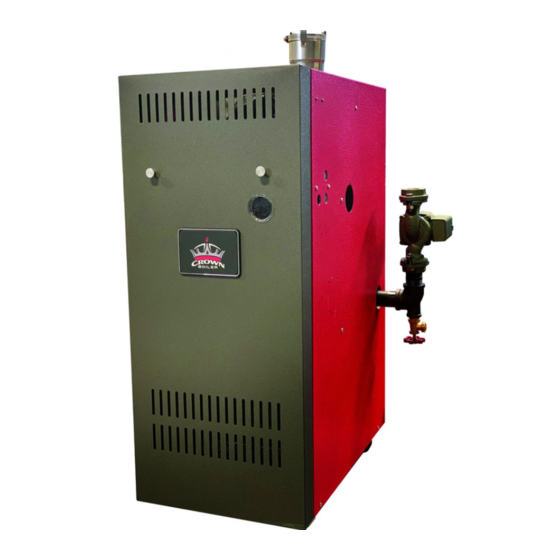
Specifications Figure 2.1: General Configuration Table 2.2: Specifications BWF Space Heating Ratings Connection Size Approx. Optional ‘A’ Water Shipping Direct Vent Width Content Net AHRI Weight Heating Basic Input Rating, AFUE Vent Capacity Boiler Fuel Water Model (inch) (NPT) (inch) (gal) (lbs) (PN) -
Page 6: Pre-Installation
Pre-Installation Make sure the boiler is configured for the correct WARNING gas (Natural or LP). Carefully read all instructions before installing For high altitude installation above 2,000 ft., see boiler. Failure to follow all instructions in proper Appendix B. order can cause personal injury or death. NOTICE: This boiler is not approved for use in A. -
Page 7: Locating The Boiler
Locating the Boiler • Provide practical service clearances. A 24” WARNING service clearance from the jacket is Failure to observe the following location recommended on the left, right, and front requirements could result in a fire, explosion or of the boiler. These clearances may be carbon monoxide (CO) hazard. -
Page 8: Air For Combustion And Ventilation
Air for Combustion and Ventilation 4. Locating the Boiler (continued) Do not install this boiler on carpeting. This may NOTICE: If combustion air is being brought cause a fire. to this boiler using one of the Direct Vent Kits shown in Table 2.2, requirements in Section 5 do G. - Page 9 5. Air for Combustion and Ventilation (continued) This section describes methods for using indoor • If the total volume of both the boiler room combustion air. Usually, when this method is not and the room to which the openings possible, the best approach will be to use the direct connect is less than 50 cubic feet per vent kit.
- Page 10 5. Air for Combustion and Ventilation (continued) B. Using Outdoor Combustion Air (“Direct Venting”) Example: A 105000 BTU/hr input boiler and a This method requires the optional kit shown in Table water heater are to be installed in a room 2.2.
-
Page 11: Venting
Venting designed to provide a gas tight seal at all WARNING joints and seams so that flue gas does not Asphyxiation Hazard. Failure to vent this boiler enter the building. Each approved vent in accordance with these instructions could system has unique method for installation - do cause products of combustion to enter the not attempt to mix components from different building resulting in severe property damage,... - Page 12 6. Vent System Design (continued) Table 6.1: Summary Of Venting Options Using Indoor Combustion Air (See Appendix A for Options Using Outdoor Air) Classification Used in this Manual Horizontal Direct Exhaust Vertical Direct Exhaust Vent Option # Illustrated in Figure Wall Wall Roof...
- Page 13 6. Vent System Design (continued) Figure 6.2: Horizontal Direct Exhaust Vent System (Vent Options 1, 2) Figure 6.4: Optional Miter Terminal Figure 6.3: Tee Terminal (BWF063 - 175 Only) 109836-01 - 04/20...
- Page 14 6. Vent System Design (continued) 5. Terminal Offsets - Tee terminals may be offset 8. Wall Thimbles – Wall thimbles are required by as much as 7 ft as shown in Figure 6.5. where the vent pipe passes through This sometimes helps maintain the 12” combustible walls with less than the required minimum clearance required above the clearance shown in Figure 4.1 or as required...
- Page 15 6. Vent System Design (continued) Figure 6.6: Vertical Direct Exhaust System (Vent Options 3, 4) 109836-01 - 04/20...
- Page 16 6. Vent System Design (continued) Table 6.7: Permissible Vent Systems And Principle Vent Components CONDENSATE WALL HORIZONTAL VERTICAL MANUFACTURER VENT SYSTEM SIZE TRAP THIMBLES TERMINATION TERMINATION 7393GC 9321 TEE: 7390TEE 7393GCS 5300CI (NOTE 2) SAF-T VENT 5391CI HEAT FAB EZ SEAL 7493GC 9421 7493GCS...
- Page 17 6. Vent System Design (continued) Figure 6.9a: Location of Vent Terminal Relative to Windows, Doors and Grades Figure 6.9b: Location of Vent Terminal Relative to Meters and Forced Air Inlets 109836-01 - 04/20...
- Page 18 6. Vent System Design (continued) Max. Overhang 0 - 12" NOT PERMITTED 12 - 48" 17 - 29" X minus 7" Greater than 48" 17 - 29" 36" Note: Overhang may not be ventilated if 'Y' is less than 48" Figure 6.9c: Location of Vent Terminal Under Overhangs 109836-01 - 04/20...
- Page 19 6. Removing Boiler from Common Chimney of the National Fuel Gas Code, ANSI Z223.1/ B. Removing Boiler From Common Chimney NFPA 54 and/or the Natural Gas and Propane When an existing boiler is removed from a Installation Code, CAN/CSA B149.1. common venting system, the common venting system is likely to be too large for proper venting WARNING...
- Page 20 6. Removing Boiler from Common Chimney (continued) C. Vent/Intake System Assembly Une fois qu’il a été déterminé, selon la 1. General Assembly Notes: méthode indiquée ci-dessus, que chaque a. Where the use of “silicone” is called for in the appareil raccordé au système following instructions, use GE RTV 106 for the d’évacuation est mis à...
- Page 21 6. Vent/Intake System Assembly (continued) 4. Complete the rest of the vent system in d. On the male end of the pipe, apply a ¼” accordance with the vent manufacturer’s wide bead of high temperature silicone instructions. approximately ½ inch from the male end of the pipe.
-
Page 22: Water Piping
Water Piping A. Standard Piping WARNING Figure 7.3 shows typical boiler system • Failure to properly pipe boiler may result in connections on a single zone system. Additional improper operation and damage to boiler or information on hydronic system design may be building. - Page 23 7. Water Piping (continued) not run relief valve discharge piping through an 5. Automatic Air Vent (Required) - At least one area that is prone to freezing. The termination automatic air vent is required. Manual vents will of the relief valve discharge piping must be usually be required in other parts of the system in an area where it is not likely to become to remove air during initial fill.
- Page 24 7. Water Piping (continued) 7. Manual Reset High Limit (Required by some 11. Alternate Return Tapping - An unplugged codes) - This control is required by ASME 1-1/4” return tapping is provided on the left CSD-1 and some other codes. Install the high side of the boiler (see “Piping for Special limit in the boiler supply piping just beyond Situations”...
- Page 25 7. Water Piping (continued) 2. Indirect Water Heaters - Figure 7.4 shows 4. Low Temperature Systems - Some systems, typical indirect water heater piping. Boiler such as radiant tubing systems, require the piping is the same as for any two-zone system. system water temperature to be limited to Figure 7.4 shows circulator zoning, which is a value below the temperature of the water...
- Page 26 7. Water Piping (continued) 5. Systems Containing Oxygen - Many hydronic 6. Piping with a Chiller - If the boiler is used systems contain enough dissolved oxygen in conjunction with a chiller, pipe the boiler to cause severe corrosion damage to a cast and chiller in parallel.
-
Page 27: Gas Piping
Gas Piping b. Use thread compounds (pipe dope) resistant WARNING to action of liquefied petroleum gas. • Shut off gas supply before servicing the boiler. c. Install sediment trap, ground-joint union and • All gas piping must be gas tight. Use thread manual shut-off valve upstream of boiler gas compound that is listed for gas service on all control valve. - Page 28 8. Gas Piping (continued) WARNING • If gas pressure in the building is above ½ psig (3.5 kPa), an additional gas pressure regulator is required. Using one additional regulator for multiple gas appliances may result in unsafe boiler operation. The additional regulator must be able to properly regulate gas pressure at the input of the smallest appliance.
-
Page 29: Wiring
Wiring WARNING 1. Line Voltage (120 VAC) Field Connections – See • All wiring and grounding must be done in Figure 9.1 for line voltage connections. Provide a accordance with the authority having jurisdiction dedicated circuit for the boiler of 15A or greater. or, in the absence of such requirements, with A service switch is recommended and is required the National Electrical Code (ANSI/NFPA 70). - Page 30 9. Wiring (continued) c. Auxiliary Limit Jumper - Used to connect CAUTION auxiliary limit device. If no such devices are • When making low voltage connections, make installed, the factory supplied jumper shown in sure that no external power source is present in Figures 9.2 and 9.3 must be installed for boiler the thermostat circuits.
- Page 31 9. Wiring (continued) Overcurrent Service Internal J-Box Power Green Ground Protection/ Switch Supply Screw Disconnect (optional) 120/60/1 (By Installer) (By Installer) Ground Terminal System On Gas Valve Circulator Circulator (By Others) Boiler Control 1 2 3 Boiler Limit Temperature L2 GND L1 Sensor ENVIRACOM 11.0...
- Page 32 9. Wiring (continued) Power Supply 120 / 60 / 1 (By Installer) Internal Internal Junction Junction Overcurrent Protection / Disconnect (By Installer) Service Switch (optional) (By Installer) Boiler Control On/Off System Circulator System Circulator Line Input Neutral On/Off DHW Circulator DHW Circulator (Supplied by Others) On/Off...
-
Page 33: Start-Up And Checkout
Start-up and Checkout WARNING Do not leave the boiler in service if it fails any of the following start-up checks. Doing so may result in fire, explosion, or carbon monoxide (CO) poisoning. WARNING • Gas leaks may result in fire or explosion. •... - Page 34 10. Start-up and Checkout (continued) FOR YOUR SAFETY READ BEFORE OPERATING WARNING: If you do not follow these instructions exactly, a fire or explosion may result causing property damage, personal injury or loss of life. A. This appliance is equipped with an ignition If you cannot reach your gas supplier, call device which automatically lights the pilot.
- Page 35 10. Start-up and Checkout (continued) appliances on and off. The inlet pressure at the boiler must be within the following limits regardless of what combination of appliances is firing: Inlet Press Natural Gas LP Gas (inches w.c.) Minimum 11.0 Maximum 14.0 14.0 3.
- Page 36 10. Start-up and Checkout (continued) its maximum setting, set the thermostat to call for heat. Allow the boiler to fire for at least an hour or until the odor from the cornstarch has dissipated. 3. Return the high limit and thermostat to their desired settings.
-
Page 37: Operation
Operation A. Controls 2. Operating Mode - Provides additional information about the current status of the 1. This boiler uses a proprietary version of the boiler. Operating mode is entered by pressing Honeywell S9361A “integrated boiler control” the I button shown in Figure 11.1. When this to manage all boiler functions including button is first pressed in Status mode, the flame supervision, temperature control, and... - Page 38 11. Operation (continued) Figure 11.2: Boiler Control Menu STATUS MODE: =Current Status (Table 11.3) Press and Hold I, ↑, and ↓ for at least 3 sec to enter ADJUSTMENT MODE Press I to enter OPERATING MODE = Current Boiler Temp. = High Limit Setting = Current Set Point = Limit Differential ...
- Page 39 11. Operation (continued) Table 11.3: Status Codes Status # Description Meaning No call for heat or DHW Call for heat present , but boiler is in thermal purge (See on page 40) Standby Call for heat/DHW present but boiler temperature is above high limit (HL) set- ting.
- Page 40 11. Operation (continued) Table 11.5: Operating Mode Parameters Parameter # Description Meaning Boiler Temperature Current boiler water temperature measured by the control’s sensor. Current target temperature (always the same as the high limit setting un- Boiler water set point less Crown outdoor reset card option is installed). Boiler will stop firing if boiler water temperature exceeds this value High Limit Set point (Circulator/s will continue to operate)
- Page 41 11. Operation (continued) something other than zero. Before doing so, verify WARNING that the system will permit flow (e.g. flow is not Improper adjustments to control parameters completely cut-off by closed zone valves) and that could result in unreliable boiler operation, the overrun will not cause overheating problems.
- Page 42 11. Operation (continued) hard lockout (as an alternative to momentarily bAc (Return to Status mode) - Exits adjustment interrupting power to the control). Pressing the up mode. Any changes made to the parameters key will turn rst momentarily to on. When it goes described above are saved, and become back off (typically within one or two seconds), the effective, as soon as they are made;...
- Page 43 11. Operation (continued) D. Sequence Of Operation 6. The control starts an ignition spark at the pilot and applies 24 volts across the pilot valve (Refer to Figures 9.3 or 9.4 for Connection and (terminals PV and MV/PV on the gas valve). Ladder diagrams) 7.
- Page 44 12. Operation (continued) E. Safety Control Operation Air Pressure Switch (APS) - The APS proves that the fan is running before allowing the ignition sequence to proceed. Failure of this switch to close is usually the result of a problem with the vent system, such as a blockage, or a problem with the fan.
-
Page 45: Service And Maintenance
Installation, Operating & Service Manual SERIES 2E Service and Maintenance Service and Maintenance Important Product Safety Information: Refractory Ceramic Fiber Product WARNING Some boiler components use materials that contain refractory ceramic fibers (RCF). RCF has been classified as a possible human carcinogen. When exposed to elevated temperatures, RCF may change into crystalline silica, a known carcinogen. - Page 46 12. Service and Maintenance (continued) A. Annual Maintenance WARNING 1. Turn off electrical power and gas supply to the • Label all wires prior to disconnection when boiler. servicing controls. Wiring errors can cause improper and dangerous operation. Verify 2. Inspect the flue passages for signs of blockage. proper operation after servicing.
- Page 47 12. Service and Maintenance (continued) WARNING Soot deposits in the flue passages are a sign that the boiler may be operating at high carbon monoxide (CO) levels. After cleaning the boiler of soot deposits, check the CO level in the flue gas to insure that the boiler is operating properly.
- Page 48 12. Service and Maintenance (continued) 11. Clean the flue passageways using a stiff bristle C. Service Notes brush. Be certain that all foreign material is 1. Pressure Switch – This boiler is equipped with a removed from the gaps between the pins. differential pressure switch which makes when there is adequate flue gas flow through the 12.
- Page 49 12. Service and Maintenance (continued) Figure 12.3a: Pressure Switch Connections Figure 12.3b: Measuring Pressure Across Pressure Switch 109836-01 - 04/20...
-
Page 50: Troubleshooting
Troubleshooting A. Before Troubleshooting B. If The Display Is Blank The following pages contain troubleshooting 1. Check for 24 VAC on transformer secondary tables for use in diagnosing control problems. connections (pink and brown wires). If voltage When using these tables the following should be across these screws is between 18 and 30 kept in mind: VAC, possible causes include:... - Page 51 13. Troubleshooting (continued) Table 13.0: Error Codes Error Code Meaning Possible Cause • Jumped air pressure switch Pressure Switch failed to open • Condensate in air pressure switch or switch tubing • Defective air pressure switch • Low gas pressure at gas valve inlet •...
- Page 52 13. Troubleshooting (continued) Table 13.1: Faults Without Error Code Present Displayed Codes Problem Possible Cause • Thermostat/s not calling for heat StA 1 Burners and • Loose connection in thermostat, zone valve end switch, or zone panel wiring. tt OFF Circulator Off •...
-
Page 53: Service Parts
Service Parts All Service Parts may be obtained through your local Crown distributor. Should you require assistance in locating a Crown distributor in your area, or have questions regarding the availability of products or service parts, please contact us at (215) 535-8900 or Fax (215) 535-9736. Main burner orifice and pressure switches shown are for sea level configured boilers. - Page 54 14. Service Parts (continued) WARNING If base must be replaced, there is a good chance pilot assembly and pilot tubing will need to be replaced as well. Replacement pilot assemblies are shown on page 54. Also check condition of manifold and gas valve and replace if they show any signs of heat, corrosion, or water damage.
- Page 55 14. Service Parts (continued) Part Number [Quantity] Description 3 Section 4 Section 5 Section 6 Section 7 Section 8 Section Gas Valve (Natural Gas), 3507020 [1] VR8204C6000 Gas Valve (Natural Gas), 109882-01 [1] VR8304P4553 Gas Valve (LP Gas), 3507220 [1] VR8204C6018 Gas Valve (LP Gas), 3507240 [1]...
- Page 56 14. Service Parts (continued) Part Number [Quantity] Description 3 Section 4 Section 5 Section 6 Section 7 Section 8 Section 109361-03 109361-04 109361-05 109361-06 109361-07 109361-08 Canopy Assembly Canopy Gasket Kit 6206001 [1] Lock Washer, #10 Split 110089-01 [1] Machine Screw, #10-24 x2-1/2" Fan Gasket Fan Gasket Only 8206085 [1]...
- Page 57 14. Service Parts (continued) Part Number [Quantity] Description 3 Section 4 Section 5 Section 6 Section 7 Section 8 Section 102033-03 102033-04 102033-05 102033-06 102033-07 102033-08 Burner Cover (Natural Gas Only) 109836-01 - 04/20...
- Page 58 14. Service Parts (continued) Part Number [Quantity] Key No. Description 3 Section 4 Section 5 Section 6 Section 7 Section 8 Section Integrated Boiler Control 3505065 [1] (Honeywell S9361A2077) Transformer 106034-01 [1] (Honeywell AT140B1297) Hydrolevel IDL 1200 LWCO 450608 [1] Control Bracket 109353-01 [1] Sensor Clamp...
- Page 59 14. Service Parts (continued) Part Number [Quantity] Description 3 Section 4 Section 5 Section 6 Section 7 Section 8 Section 109378-03 109378-04 109378-05 109378-06 109378-07 109378-08 Rear Jacket Panel Left Jacket Panel 660301 [1] Right Jacket Panel 660300 [1] Vestibule Jacket Panel 661333 [1] 661334 [1] 661335 [1]...
- Page 60 14. Service Parts (continued) Part Number [Quantity] Description 3 Section 4 Section 5 Section 6 Section 7 Section 8 Section Temperature/Pressure Gauge 95-038 [1] 1/2” Short Electrowell 450353 [1] (Hydrolevel 48-221)* 3/4" Safety Relief Valve 95-040 [1] (30 psi) Boiler Drain Valve 95-041 [1] Air Pressure Switch 109839-01 [1]...
- Page 61 14. Service Parts (continued) Part Number [Quantity] Key No. Description Section Section Section Section Section Section Line Voltage Wire Harness 110012-01 [1] 110011-01 [1] Low Voltage Wire Harness 110010-01 [1] 109836-01 - 04/20...
-
Page 62: Appendix A: Direct Venting This Boiler
Appendix A: Direct Vent Installations B. Intake System Design - This Appendix describes how to bring combustion air directly from outside to the boiler 1. Intake Piping Materials – Any of the following (direct venting) using the direct vent kits shown materials may be used between the intake in Table 2.2. - Page 63 Appendix A (continued) Table A.2: Summary Of Direct Vent Options (See Section 6 for Additional Details on Vent System Installation) Classification Used in this Horizontal Direct Vent Vertical Direct Vent Manual Vent Option # Illustrated in Figure A.3, A.4 A.3, A.4 A.3, A.4 A.6, A.7 A.6, A.7...
- Page 64 Appendix A (continued) Figure A.4: Horizontal Direct Venting (Vent Options 5-7) b. Vertical systems use either the terminal 5. Vertical terminal location - Install the intake provided with this kit or a 180 degree terminal as shown in Figure A.6 or A.7. elbow (either a single fitting or two 90 The vertical distance between vent and air degree elbows) as shown in Figure...
- Page 65 Appendix A (continued) Figure A.5: Horizontal Terminal Offsets Figure A.6: Vertical Direct Vent System (Vent Options 8-10) 109836-01 - 04/20...
- Page 66 Appendix A (continued) C. Air Intake System Assembly - 4. If PVC is used for the intake system, the PVC will fit over the outside of the air intake collar 1. If PVC piping is used, use PVC cement to on the boiler.
-
Page 67: Appendix B: Instructions For High Altitude Installations
Appendix B: Instructions for High Altitude Installations (US Only) These instructions apply only to the following altitude ranges: Sea Level - 2000ft, 2001 - 10,200ft These instructions contain specific information to setup your boiler to ensure proper operation. Table B.1 lists the specific differences between As with most gas appliances, special consideration sea level and high altitude configurations. - Page 68 Appendix B (continued) Figure B.2: Air Intake Terminal (Installed on Air Intake Collar) WARNING • Safe operation of this boiler depends upon the use of the correct burner orifice AND pressure switch for the altitude at which the boiler is to be installed. See Table B.1 for the correct configuration. Failure to properly configure this boiler for the installation altitude could cause personal injury or death due to carbon monoxide (CO) poisoning.
-
Page 69: Appendix C: Special Requirements For Side-Wall Vented Appliances In The Commonwealth Of Massachusetts
Appendix C: Special Requirements For Side-Wall Vented Appliances In The Commonwealth of Massachusetts IMPORTANT The Commonwealth of Massachusetts requires compliance with regulation 248 CMR 4.00 and 5.00 for installation of side-wall vented gas appliances as follows: 1. For direct-vent appliances, mechanical-vent heating appliances or domestic hot water equipment, where the bottom of the vent terminal and the air intake is installed below four feet above grade the fol- lowing requirements must be satisfied: a. - Page 70 SERVICE RECORD DATE SERVICE PERFORMED 109836-01 - 04/20...
- Page 71 Notes 109836-01 - 04/20...
- Page 72 Notes Crown Boiler Company, Inc. P.O. Box 14818 Philadelphia, PA 19134 1-215-535-8900 www.crownboiler.com 109836-01 - 04/20...
Need help?
Do you have a question about the BWF Series and is the answer not in the manual?
Questions and answers