Table of Contents
Advertisement
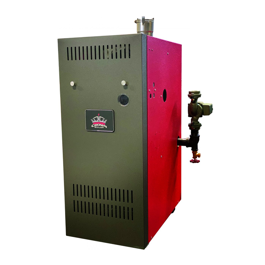
BWF Series
Gas-Fired Fan Assisted Hot Water Boilers
INSTALLATION INSTRUCTIONS
These instructions must be affixed on or adjacent to the boiler
Models:
BWF061
•
BWF095
•
BWF128
•
BWF162
•
BWF195
•
BWF229
•
CROWN
Boiler Co
Manufacturer of Hydronic Heating Products
P.O. Box 14818 3633 I. Street
Philadelphia, PA 19134
Tel: (215) 535-8900 • Fax: (215) 535-9736 • www.crownboiler.com
WARNING: Improper installa-
tion, adjustment, alteration,
service or maintenance can
cause property damage, injury,
or loss of life. For assistance or
additional information, consult a
qualified installer, service
agency or the gas supplier.
This boiler requires a special
venting system. Read these
instructions carefully before
installing.
Advertisement
Table of Contents

Related Manuals for Crown Boiler BWF095


Summary of Contents for Crown Boiler BWF095
-
Page 1: Installation Instructions
BWF Series Gas-Fired Fan Assisted Hot Water Boilers INSTALLATION INSTRUCTIONS These instructions must be affixed on or adjacent to the boiler Tel: (215) 535-8900 • Fax: (215) 535-9736 • www.crownboiler.com Models: BWF061 • BWF095 • BWF128 • BWF162 • BWF195 •... -
Page 2: Table Of Contents
Table of Contents Product Description………………………... 2 II Specifications……………………………….. 2 III Before Installing…………………………….. 3 IV Locating the Boiler………………………….. 3 V Air for Combustion and Ventilation………… 5 VI Venting………………………………………. 9 Horizontal Vent System Design……….. 9 Vertical Vent System Design…………... 14 Vent System Assembly…………………. 18 VII Gas Piping…………………………………... -
Page 3: I Product Description
The BWF series boiler is a cast iron gas fired boiler designed for use in forced hot water heating systems. The BWF is intended for installations where a usable chimney is not available. The BWF is normally vented using an approved vertical or horizontal AL29-4C stainless steel venting system, which is not included with the boiler. -
Page 4: Before Installing
• A 24” service clearance from the jacket is recommended on the left, right, and front of the boiler. These clearances may be reduced to those shown in Figure 2, however servicing the boiler will become increasingly difficult as these service clearances are reduced. - Page 5 3) Do not install this boiler in an area where large amounts of airborne dust will be present, such as a workshop. Do not install in a location where sources of hydrocarbons will be stored or used. Some common sources of hydrocarbons include bleaches, fabric softeners, paints, cleaners, refrigerants, and cat boxes.
-
Page 6: Air For Combustion And Ventilation
If doors are installed between the boiler room and an adjoining space, do not consider the volume of the adjoining space, even if the door is normally left open. Divide the volume of the boiler room by the input in thousands of BTU/hr. If the result is less than 50, the boiler room is a confined space. - Page 7 If the boiler is in a confined space – Provide two openings into the boiler room, one near the floor and one near the ceiling. The top edge of the upper opening must be within 12” of the ceiling and the bottom edge of the lower opening must be within 12”...
-
Page 10: Venting
Chimney venting using a masonry or “B” vent chimney and a special Category I Vent Kit available from Crown. DO NOT ATTEMPT TO VENT A BWF SERIES BOILER INTO A MASONRY OR “B” VENT CHIMNEY WITHOUT THE CROWN CATEGORY I VENT KIT SHOWN IN TABLE III Table 3 summarizes these three venting options. - Page 11 1 termination elbow Since the boiler is a BWF162, all piping must be done in 3” pipe. The first 90 degree elbow and the termination elbow are not considered. From Table 4, the equivalent length of the 3” 45 elbow is 4.5ft. The equivalent length of the 3”...
- Page 12 9) Condensate traps –In some horizontal installations, condensate traps may be needed to prevent condensate from running into the boiler or collecting in the vent system. A condensate trap must be used if the horizontal piping does not have a continuous slope to the outside.
- Page 13 • If possible, install the terminal on a wall away from the prevailing wind. Reliable operation of this boiler cannot be guaranteed if the terminal is subjected to winds in excess of 40 mph.
-
Page 15: Vertical Vent System Design
1) See Figure 13 for the general vertical stainless steel venting configuration. For the purposes of this manual, a “vertical exhaust system” is a Category III vent system that exits the structure through a roof. 2) Approved Systems – Use one of these four approved vent systems: •... - Page 16 1 Cap Since the boiler is a BWF162, all piping must be done in 3” pipe. The first two 90 elbows and the termination cap are not considered. The condensate trap is treated as a straight length of pipe 1.5 feet in length. The result is 13.5 ft of straight pipe and two 45 elbows.
- Page 17 11) Piping supports – Vertical and horizontal sections of piping must be properly supported. See the “Vent System Assembly” section of this manual for more information. 12) Location of vent cap– The lowest discharge opening on the cap must be at least 2 feet above any object located within 10 feet (Fig.
- Page 18 Removing an Existing Boiler From a Common Chimney In some cases, when an existing boiler is removed from a common chimney, the common venting system may be too large for the remaining appliances. At the time of removal of an existing boiler, the following steps shall be followed with each appliance remaining connected to the common venting system placed in operation, while the other appliances remaining connected to the common venting system are not in operation.
-
Page 19: Vent System Assembly
10-32 mounting screws. Verify that the model number marked on the outlet exhaust orifice matches that of the boiler being installed. Mount the collar and orifice as shown in Figure 15. If desired, the first piece of exhaust pipe can be connected to the collar before mounting the collar on the boiler. - Page 20 Clean the exterior of the male end of the first piece of pipe and the inside of the vent collar on the boiler. Use a cleaner such as Methyl Ethyl Keytone (MEK) or naptha.
- Page 21 Clean the exterior of the male end of the first piece of pipe and the inside of the vent collar on the boiler. Remove dirt, grease, and moisture from the surfaces to be sealed. Dry surfaces or allow to dry thoroughly.
- Page 22 Smooth out the excess silicone. Use one of the following Z-Flex locking bands to mechanically secure the vent pipe to the terminal: SVE Series III Nominal Size 3” 4” n) Allow the silicone to cure for 24 hours before operating the boiler. Z-Flex # 2SVSLBF03 2SVSLBF04...
- Page 23 Cut the male “spigot” off of the first piece of pipe (Fig 21). If necessary, crimp the cut end of the pipe so that it can be inserted at least 1” into the collar. d) Clean the exterior of the male end of the first piece of pipe and the inside of the vent collar on the boiler with an alcohol pad.
- Page 24 Clean the exterior of the male end of the first piece of pipe and the inside of the vent collar on the boiler. Remove dirt, grease, and moisture from the surfaces to be sealed. Dry surfaces or allow to dry thoroughly.
- Page 25 1 ¾”. Tighten the hose clamp to mechanically lock the pipe onto the terminal. Apply and smooth silicone over the outside of the joint including the hose clamp in the FasNSeal pipe. n) Allow the silicone to cure for 24 hours before operating the boiler. 8) Condensate Traps: a) Trap should have the basic configuration shown in Figure 25.
-
Page 26: Gas Piping
Gas piping to the boiler must be sized to deliver adequate gas for the boiler to fire at the nameplate input at a line pressure between the minimum and maximum values shown on the rating plate. For more information on gas line sizing, consult the utility or Part 2 of the National Fuel Gas Code. -
Page 27: System Piping
Berkely Heights, NJ. The components in this system and their purposes are as follows: 1) Relief valve (Required) – Mount the relief valve in the ¾ tapping on the right side of the boiler as shown in Figure 1 using the ¾... -
Page 28: Piping For Special Situations
9) Isolation Valves (Optional) – Isolation valves are useful if the boiler must be drained, as they will eliminate having to drain and refill the entire system. 10) Drain Valve – The drain valve is shipped in the boiler parts bag. Install it in the ¾” opening in the tee on the boiler return (Figure 1). - Page 29 5) Piping with a Chiller – If the boiler is used in conjunction with a chiller, pipe the boiler and chiller in parallel as shown in Figure 31. Use isolation valves to prevent chilled water from entering the boiler.
- Page 30 6) Air Handlers – Where the boiler is connected to air handlers through which refrigerated air passes, use flow control valves in the boiler piping or other automatic means to prevent gravity circulation during the cooling cycle.
-
Page 32: Wiring
• Green – Ground connection 2) The circulator is factory wired. If a different circulator is wired to the boiler, its full load current draw must not exceed 12A. 3) Connect the 24-volt thermostat to terminals “R” and “G” on the R8285 fan center. Set the heat anticipator to 0.34 Amps. - Page 33 R845A using the “X” and “X” terminals in place of the “5” and “6” terminals on a R845A. A call for heat from the “zone #1” thermostat causes the zone #1 circulator to start and the boiler to fire exactly as in a single zone system (see “Sequence of Operation”).
- Page 35 9) At the end of a burner cycle, the normally closed contacts on the vacuum switch should make after the fan is de- energized. If this does not happen, there will be no current path to relay coil 2K upon the next call for heat and the boiler will not fire.
-
Page 37: Start-Up And Checkout
The combustion chamber insulation panels in this boiler contain a cornstarch based binder which may emit a strong odor as it is burned out of the insulation when the boiler is fired for the first time. An hour or more of continuous firing may be required to burn off all of this binder. -
Page 38: Operating Instructions
FOR YOUR SAFETY READ BEFORE LIGHTING WARNING: If you do not follow these instructions exactly, a fire or explosion may result causing property damage, personal injury or loss of life. A. This appliance is equipped with an ignition device which automatically lights the pilot. try to light the pilot by hand. - Page 39 “Spark” terminal on the ignition module. Both the main and pilot flames should extinguish immediately. 9) Allow the boiler temperature to increase to the high limit setting. Confirm that the high limit shuts down the burners and the combustion fan.
- Page 40 FIGURE 38: PILOT BURNER FLAME...
-
Page 41: Service And Maintenance
10) Inspect the vacuum switch hose for deterioration. Clean out any condensate or other blockage found in this tube. 11) Disconnect the vent system from the boiler using the four 10-32 screws in the vent collar. Inspect the blower wheel and fan housing for corrosion damage. -
Page 42: Service Notes
Table 8 shows typical and maximum readings for CO and CO2 on both natural and LP gas. Do not leave the boiler in operation if either the CO or CO2 exceeds the maximum limit in this table. Some causes of excessive CO or CO2 include: •... - Page 43 3) Vacuum Switch – This boiler is equipped with a vacuum switch that is designed to prevent burner operation if the combustion fan does not operate properly or there is a blockage in the vent system. This switch “makes” (permits burner operation) as the vacuum increases.
-
Page 44: Troubleshooting Charts
48 volts across the relay coil. In older buildings, this transformer may be hidden in a location far from the boiler. If this second transformer exists, it must be found and removed before the relay is... - Page 45 R8222? 24 volts present across yellow and orange connections on * Defective R8222? R8222 relay - see note 6 on page 43. * Socket not fully seated on relay * Boiler off on high limit * Defective high limit...
- Page 46 Does boiler shut down when t'stat wire is removed from terminal R on R8285? * Internal boiler wiring problem, consult Crown representative * T'stat or zone valve wiring calling for heat * T'stat wires shorted...
- Page 47 Intermittent Ignition System Troubleshooting Chart START (24 volts is present across 5 and 6 on S8670, 30-50 second prepurge period has passed, but main burners do not light) Spark across Pilot ignitor/sensor lights? gap? 24 volts across terminals 2&3 at S8670? Can you hear sparking?
-
Page 48: Parts
In some cases, the following parts lists do not include Crown part numbers because they were not available at the time of printing. Order these parts by their description, specifying the boiler model number on which they are to be used. - Page 50 ORIFICE HITCH PIN LOWER INJECTION SHIELD UPPER INJECTION SHIELD 1/4-20 BRASS WING NUT 10-32 x 3/16" SCREW * NOT PICTURED QTY. OR QUANTITY PER BOILER OR CROWN P.N. CROWN P.N. 150500 1 ea. 1 ea. 150501 2 ea. 4 ea.
- Page 51 1” Burner Components 50mm Burner Components...
- Page 52 BWF WIRE HARNESS #4 (RED) BWF WIRE HARNESS #5 (ORANGE) INTERMITTENT IGNITION HARNESS IGNITION GROUND WIRE HARNESS * NOT PICTURED CAUTION QTY. OR QUANTITY PER BOILER OR CROWN P.N. CROWN P.N. 650301 1 ea. 1 ea. 650300 1 ea. 1 ea.
- Page 54 CROWN Boiler Co Manufacturer of Hydronic Heating Products P.O. Box 14818 3633 I. Street Philadelphia, PA 19134 Tel: (215) 535-8900 • Fax: (215) 535-9736 • www.crownboiler.com...
Need help?
Do you have a question about the BWF095 and is the answer not in the manual?
Questions and answers