Table of Contents
Advertisement
Quick Links
Advertisement
Table of Contents

Related Manuals for RS PRO RS-136


Summary of Contents for RS PRO RS-136
- Page 1 Instruction Manual RS-136 Temperature Calibrator (RTD + TC)
- Page 2 Temperature Calibrator (RTD + TC) / EN _________________________________________________________________________________ EN 61326-1 : 2013 Please read the statement thoroughly to prevent injury or loss of life, and prevent damage to this product. Earth (ground) Conforms to relevant European Union directives. Do not dispose of this instrument as unsorted municipal waste.
-
Page 3: Table Of Contents
Temperature Calibrator (RTD + TC) / EN _________________________________________________________________________________ Table of Contents FEATURES ........................ 1 II. PANEL DESCRIPTION ....................2 III. OPERATION ........................ 5 3.1 S (4W, 3W, 2W) ..............5 OURCE SIGNALS 3.2 S ................. 8 OURCE HERMOCOUPLE IGNALS 3.3 M RTD T .......... -
Page 4: Features
Temperature Calibrator (RTD + TC) / EN _________________________________________________________________________________ I. Features 1. High precision and combination of RTD and Thermocouple (TC) calibration 2. Source and measure 14 types of RTD and resistance 3. Source and measure 11 types of thermocouples (TC) 4. -
Page 5: Panel Description
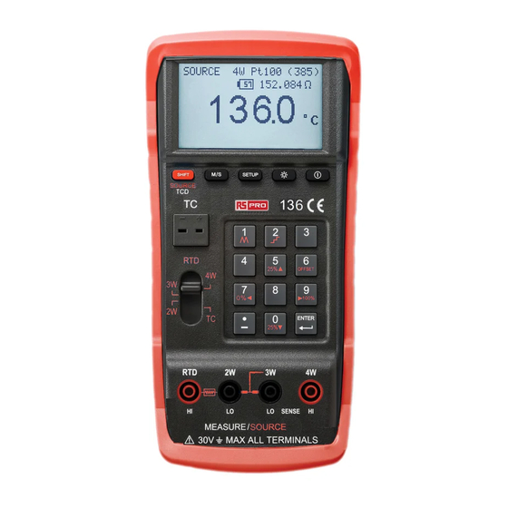
Temperature Calibrator (RTD + TC) / EN _________________________________________________________________________________ II. PANEL DESCRIPTION 1. ON/OFF button. 2. Backlight 3. SETUP button. 4. M/S button to select Measure or Source 5. Shift button to select sub-functions defined for source. Or enable thermocouple 03/27/2020 Version No. 1... - Page 6 Temperature Calibrator (RTD + TC) / EN _________________________________________________________________________________ detection (TCD) for the TC MEASURE mode. In the SETUP, press SHIFT button to clear the field for the new data entry. 6. Thermocouple (TC) input and output. 7. Sliding switch for selecting RTD connection 4W, 3W, 2W or thermocouple. 8.
- Page 7 Temperature Calibrator (RTD + TC) / EN _________________________________________________________________________________ LCD Display 1. Temperature in ℃ or ℉ 2. Corresponding Ohm 3. RTD, Resistance or TC type 4. Battery capacity in % (e.g. 57%) 5. RTD connection (4W, 3W, or 2W) 6. SOURCE or MEASURE 7.
-
Page 8: Operation
Temperature Calibrator (RTD + TC) / EN _________________________________________________________________________________ III. OPERATION 3.1 Source RTD signals (4W, 3W, 2W) 03/27/2020 Version No. 1... - Page 9 Temperature Calibrator (RTD + TC) / EN _________________________________________________________________________________ Step 1: Press M/S button to select SOURCE Step 2: Move sliding switch to select RTD connection (4W, 3W, or 2W) Step 3: Press SETUP button to select RTD type. Then press SETUP button again to exit SETUP Step 4: Enter value of temperature Step 5: Connect the calibrator to the instrument under test as shown in...
- Page 10 Temperature Calibrator (RTD + TC) / EN _________________________________________________________________________________ Note: For the SOURCE RTD 3W connection, the two sockets (LO and sense LO) need to be shorted by the stackable black test leads with banana plugs (provided). Then plug the test leads with prods into the stackable test leads.
-
Page 11: Source Thermocouple Signals
Temperature Calibrator (RTD + TC) / EN _________________________________________________________________________________ 3.2 Source Thermocouple Signals 03/27/2020 Version No. 1... - Page 12 Temperature Calibrator (RTD + TC) / EN _________________________________________________________________________________ Step 1: Press M/S button to select SOURCE Step 2: Move sliding switch to select TC (Thermocouple) Step 3: Press SETUP button to select TC type. Then press SETUP button again to exit SETUP Step 4: Connect the calibrator to the thermometer under test as shown in the Figure following Step 5: Enter value of temperature...
-
Page 13: Measure Rtd Temperature And Resistance
Temperature Calibrator (RTD + TC) / EN _________________________________________________________________________________ 3.3 Measure RTD Temperature and Resistance 03/27/2020 Version No. 1... - Page 14 Temperature Calibrator (RTD + TC) / EN _________________________________________________________________________________ Step 1: Press M/S button to select MEASURE Step 2: Move sliding switch to select RTD connection (4W, 3W, or 2W) Step 3: Press SETUP button to select RTD type. Then press SETUP button again to exit SETUP Step 4: Connect the calibrator to the RTD or resistance under test as shown in the Figure following...
- Page 15 Temperature Calibrator (RTD + TC) / EN _________________________________________________________________________________ 03/27/2020 Version No. 1...
- Page 16 Temperature Calibrator (RTD + TC) / EN _________________________________________________________________________________ Note: The inaccuracy caused by the test leads resistance is not included in the source or measure accuracy. 03/27/2020 Version No. 1...
-
Page 17: Measure Thermocouple Temperature
Temperature Calibrator (RTD + TC) / EN _________________________________________________________________________________ 3.4 Measure Thermocouple Temperature 03/27/2020 Version No. 1... - Page 18 Temperature Calibrator (RTD + TC) / EN _________________________________________________________________________________ Step 1: Press M/S button to select MEASURE Step 2: Move sliding switch to select TC (Thermocouple) Step 3: Press SETUP button to select TC type. Then press SETUP again to exit SETUP Step 4: Connect the calibrator to the thermocouple under test as shown in the Figure following Step 5: Read the value of temperature from LCD...
-
Page 19: Optimal Ohm Measurement (4W, 3W, And 2W)
Temperature Calibrator (RTD + TC) / EN _________________________________________________________________________________ 3.5 Optimal OHM measurement (4W, 3W, and 2W) Step 1: Follow the steps stated in section 3.3 and select OHM in the setup. The calibrator will automatically output optimal current for measurement of resistance. - Page 20 Temperature Calibrator (RTD + TC) / EN _________________________________________________________________________________ Step 2: If the other end is another calibrator connected to the calibrator. The other calibrator might not be able to sense the current outputted from the calibrator. Users can press button 5 to enter manual mode and change the output current.
-
Page 21: Dc Current Calibration Using Ohm Measurement Setup (4, 3, And 2W)
Temperature Calibrator (RTD + TC) / EN _________________________________________________________________________________ 3.6 DC Current calibration using OHM measurement setup (4, 3, and 2W) The calibrator can also be used to calibrate 4 values of current (100μA, 250 μA, 1mA, and 2mA). Users can enter the mode of OHM measurement and press button 5 to enter manual mode with MAN displayed on LCD. -
Page 22: Ramp And Step In Source Mode
Temperature Calibrator (RTD + TC) / EN _________________________________________________________________________________ 3.7 Ramp and Step in SOURCE mode This calibrator provides RAMP (keypad 1) and STEP (keypad 2) functions for RTD and TC in SOURCE mode. Ramp: Press SHIFT first, then press number 1. Once Ramp is selected, RAMP icon will be displayed on LCD. -
Page 23: Remove Inaccuracy Caused By The Resistance Of Test Leads In 2W
Temperature Calibrator (RTD + TC) / EN _________________________________________________________________________________ 3.8 Remove Inaccuracy caused by the resistance of test leads in 2W In the 2W connection, the resistance of test leads would add inaccuracy to the measurement or simulation of temperature or resistance. To remove the inaccuracy caused by the resistance of test leads, users can perform the OFFSET function in the 2W connection. - Page 24 Temperature Calibrator (RTD + TC) / EN _________________________________________________________________________________ symbol appears on LCD to indicate the value of test leads resistance is subtracted for any subsequent measurement. With the SHIFT symbol displayed on the LCD, users can press the OFFSET (6) button to toggle the state of OFFSET function between “ENABLE” and “DISABLE”...
- Page 25 Temperature Calibrator (RTD + TC) / EN _________________________________________________________________________________ SOURCE Step 1: Users must perform the OFFSET function in the MEASURE mode first. Step 2: Then press the M/S button to select SOURCE mode. Example: Source 25Ω with test leads resistance compensated WARNING: Once the OFFSET function is performed in 2W connection, DO NOT CHANGE the test leads used or the RTD type or resistance selected.
-
Page 26: Auto Calibration
Temperature Calibrator (RTD + TC) / EN _________________________________________________________________________________ 3.9 Auto Calibration Whenever users move the sliding switch (RTD 4W, 3W, 2W, TC), enter and exit from SETUP, or press M/S button to change MEASURE or SOURCE mode, the calibrator will always re-calibrate itself to ensure the accuracy. Users shall see the text of “CAL..1 …”... -
Page 27: Setup
Temperature Calibrator (RTD + TC) / EN _________________________________________________________________________________ IV. SETUP Press SETUP button to enter setup pages. There are two pages of setup Page 1: Page 2: Press ▲ (5) or ▼ (0) to select item Once selected, the item is displayed in reverse video Press◄(7) or ►(9) to change RTD type, TC type, UNIT ( ℃... -
Page 28: Select Rtd Type Or Resistance
Temperature Calibrator (RTD + TC) / EN _________________________________________________________________________________ 4.1 Select RTD type or resistance Step 1: press SETUP to enter SETUP Step 2: press ▲ ▼ to select the item of RTD type Step 3: press ◄►to select desired RTD type Step 4: press SETUP again to exit 4.2 Select TC type Step 1: press SETUP to enter SETUP... -
Page 29: Select Unit (℃ Or ℉)
Temperature Calibrator (RTD + TC) / EN _________________________________________________________________________________ 4.3 Select UNIT ( ℃ or ℉ ) Step 1: press SETUP to enter SETUP Step 2: press ▲ ▼ to select the item of UNIT Step 3: press ◄►to select desired unit of ℃ or ℉ Step 4: press SETUP again to exit 4.4 Enter the values of Cold Junction Compensation Step 1: press SETUP to enter SETUP... -
Page 30: Enter The Values Of Rtd 0% And 100
Temperature Calibrator (RTD + TC) / EN _________________________________________________________________________________ 4.5 Enter the values of RTD 0% and 100% Step 1: press SETUP to enter SETUP Step 2: press ▲ ▼ to select item of RTD 0% or 100% Step 3: press SHIFT to clear input field Step 4. -
Page 31: Auto-Power-Off
Temperature Calibrator (RTD + TC) / EN _________________________________________________________________________________ 4.7 Auto-Power-Off Step 1: press SETUP to enter SETUP Step 2: press ▲ ▼ to select item of AutoPowerOff Step 3: press ◄►to enable or disable Step 4: press SETUP again to exit 4.8 Restore Factory Settings Step 1: press SETUP to enter SETUP Step 2: press ▲... -
Page 32: Electrical Specifications
Temperature Calibrator (RTD + TC) / EN _________________________________________________________________________________ V. ELECTRICAL SPECIFICATIONS Specifications apply from +18 °C to +28 °C unless stated otherwise. All specifications assume a 5-minute warm-up period. Ohm Measure: Range(Ω) Resolution(Ω) 0.000Ω to 100.00Ω 0.001Ω 100.00Ω to 1000.0Ω 0.01Ω... - Page 33 Temperature Calibrator (RTD + TC) / EN _________________________________________________________________________________ Ohm Source (Accuracy is based upon 4W connection): Excitation Current Accuracy (% of Output Range(Ω) from Measurement + Floor) Device 0.5mA to 5mA 1.0Ω to 400.0Ω 0.015%+0.1Ω 400.0Ω to 1500.0Ω 0.05mA to 5mA 0.015%+0.5Ω...
- Page 34 Temperature Calibrator (RTD + TC) / EN _________________________________________________________________________________ (RTD Sensor inaccuracies not included; Temperature coefficient : ± 0.05 ° C/ ° C for measure,± 0.05 ° C/ ° C(<18 ° C or >28 ° C) for source) RTD Type Measure (°C) Source (α) Current...
- Page 35 Temperature Calibrator (RTD + TC) / EN _________________________________________________________________________________ RTD source in ° C: Accuracy is based upon 4W connection, driving voltage is less than 1.7V and the excitation current is based upon 0.5mA to 5mA (0 to 400 Ω ) and 0.05mA to 5mA (400 Ω...
- Page 36 Temperature Calibrator (RTD + TC) / EN _________________________________________________________________________________ RTD Resolution in ℉ : Range Resolution (measure) Resolution (source) -328°F to 32°F 0.1°F 0.1°F 32°F to 1472°F 0.1°F 0.1°F RTD measure in ℉ : RTD Type Measure (°F) Source (α) Current Range Accuracy 10 Ω...
- Page 37 Temperature Calibrator (RTD + TC) / EN _________________________________________________________________________________ RTD source in ℉ Accuracy is based upon 4W connection, driving voltage is less than 1.7V and the excitation current is based upon 0.5mA to 5mA (0 to 400Ω) and 0.05mA to 5mA (400Ωto 7000Ω).
- Page 38 Temperature Calibrator (RTD + TC) / EN _________________________________________________________________________________ Source and measure, 0.1 ℃ & 0.1 ℉ emperature of Thermocouples Resolution, Internal Cold Junction Compensation, thermocouples accuracy is not included, and 3 minutes after plugging in thermocouples. °C °F Range Accuracy Range Accuracy -200 to -150...
- Page 39 Temperature Calibrator (RTD + TC) / EN _________________________________________________________________________________ 1800 to 2310 3272 to 4190 2.16 DC Output Current in the OHM measurement Manual mode (Operating Voltage<2.5V , Open Circuit:3.7V) DC Current Accuracy of reading ±0.015% ±0.05μA 100μA ±0.015% ±0.05μA 250μA ±0.015% ±0.05μA ±0.015% ±0.05μA 03/27/2020 Version No.
-
Page 40: General Specifications
Temperature Calibrator (RTD + TC) / EN _________________________________________________________________________________ VI. GENERAL SPECIFICATIONS Dimension: 214.0(L) x 98.7(W) x 56.0(H) mm 8.4" (L) x 3.9" (W) x 2.2" (H) Battery Type 1.5V LR6 AA x 5 Power Consumption 30mA with backlight off Battery Life 60 Hours with backlight off (Alkaline type) Weight: 630g / 22.2oz (Batteries included) -
Page 41: Battery Replacement
Temperature Calibrator (RTD + TC) / EN _________________________________________________________________________________ VII. Battery Replacement When the users see the battery capacity is less or equal to 3%, users should follow the following procedures to replace the used batteries with new batteries. Step 1: Turn off the calibrator and remove all the test leads and any thermocouple from the calibrator Step 2: Remove the holster and remove the screw of the battery compartment cover. -
Page 42: Limited Warranty
Temperature Calibrator (RTD + TC) / EN _________________________________________________________________________________ Limited Warranty This meter is warranted to the original purchaser against defects in material and workmanship for 3 years from the date of purchase. During this warranty period, RS Components will, at its option, replace or repair the defective unit, subject to verification of the defect or malfunction. - Page 43 Temperature Calibrator (RTD + TC) / EN _________________________________________________________________________________ 03/27/2020 Version No. 1...
- Page 44 Africa RS Components SA P.O. Box 12182, Vorna Valley, 1686 20 Indianapolis Street, Kyalami Business Park, Kyalami, Midrand South Africa www.rs-components.com Asia RS Components Ltd Suite 1601, Level 16, Tower 1, Kowloon Commerce Centre, 51 Kwai Cheong Road, Kwai Chung, Hong Kong www.rs-components.com China...
Need help?
Do you have a question about the RS-136 and is the answer not in the manual?
Questions and answers