
Related Manuals for RS PRO RS 155B


Summary of Contents for RS PRO RS 155B
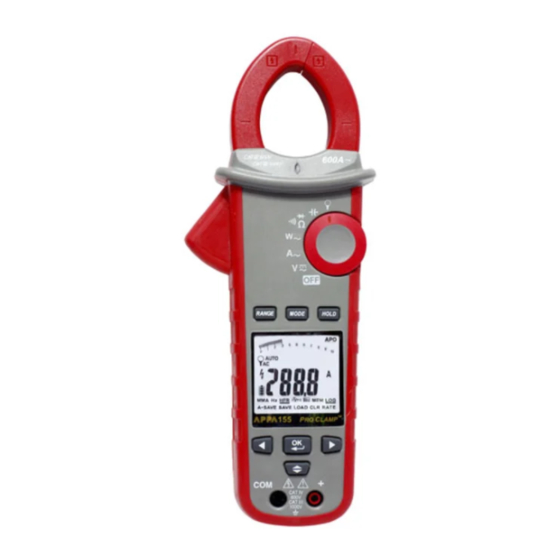
- Page 1 Instruction Manual RS 155B (162-4455) / RS 156B (162-4456) RS 157B (162-4457) / RS 158B (162-4458) Clamp Meter Press 2 sec RS 158B ...
-
Page 2: Safety Information
150B Series / EN Warning Safety sheet Warning Safety sheet ...... -
Page 3: Unsafe Voltage
150B Series / EN CAUTION ˙ Disconnect the test leads from the test points before chang- ing the position of the function rotary switch. ˙ Never connect a source of voltage with the function rotary switch in Ω, ,and position. - Page 4 150B Series / EN Feature ˙10000 Count digital display ˙Active Backlit,Large scale display ˙VoltSeek (None Contact Voltage) ˙Analog Bar graph ˙True RMS reading on AC and AC+DC mode ˙ Memory Save/Load (data amount up to 1000 ) ˙Data logger (data amount up to 9999 ) ˙Bluetooth wireless communication ˙Torch lightening when clamping ˙Auto AC/DC 1000 Amps capability and selection (For 158B)
-
Page 5: Unpacking And Inspection
150B Series / EN Unpacking and Inspection Upon removing your new Power Clamp Meter from its packing, you should have the following items: 1. Power Clamp Meter 2. Test leads. set (1 x Black, 1 x Red) 3. Temperature Probe (For 158B) 4. -
Page 6: Power On/Off
150B Series / EN Power On / Off Power on After turning on the meter, the LCD will show Full, half, and low to indicate the battery capacity. Auto Power Off After idle 15 min The meter can work again by turning it on from the OFF position. -
Page 7: Menu Operation
150B Series / EN Auto Power Off (APO) disable : Press OK button while tuning meter on from OFF position. Push Buttons Bluetooth LEFT RIGHT UP/DOWN Menu Operation Example Use arrow keys to move the blinking cursor to the target icon, and then press OK button Use arrow keys to move the blinking cursor to the target icon, and then press OK button for more than 2 seconds. -
Page 8: Making Basic Measurements
150B Series / EN Making Basic Measurements Preparation and Caution Before Measurement : Observe the rules of Warnings and Cautions The figures on the following pages show how to make basic measurements. When connecting the test leads to the DUT (Device Under Test), connect the common test lead before connecting the live lead. -
Page 9: Measuring Current
150B Series / EN Warning To avoid electrical shock, hazard or damage to meter, do not attempt to measurement that might exceed 1000 V dc or ac RMS. Do not apply more then 1000 V dc or ac RMS between the common input terminal and earth ground. -
Page 10: Auto Sense Mode
150B Series / EN AUTO SENSE mode : Display measurement result at AC only with RMS value or DC value, it depends on whichever is greater. AC mode : AC only with RMS value. DC mode : DC value. AC+DC mode : AC+DC RMS value. -
Page 11: Inrush Current
150B Series / EN ACA mode >2SEC >2SEC >2SEC In PEAK HOLD mode, the meter is activated to save the positive peak value and negative peak value. Positive peak value is displayed in PEAK MAX mode. Negative peak value is displayed in PEAK MIN mode. - Page 12 150B Series / EN DCA ZERO (For 156B/158B) Remove the jaw out of the conductor. Press HOLD Key > 2 Sec to compensate the residual magnetism. > 2 Sec - DCA Zero is only available in Auto Sense, DC and AC+DC mode.
- Page 13 150B Series / EN MAX/MIN/AVG The MAX/MIN/AVG mode records the minimum and maximum input values. When the inputs go below the record minimum value or above the record maximum value, the meter records the new value. The MAX/MIN/AVG mode can also calculate the average of reading.
-
Page 14: Harmonic Measurement
150B Series / EN Harmonic Measurement (AC mode only) THD-F=RMS of Harmonics ÷ RMS of fundamental ×100%. (harmonics up to the 25 th ) Hn=RMS of Individual Harmonic ÷ RMS of fundamental ×100%. Press RANGE button to display harmonic order or the value of the harmonic(unit : %). -
Page 15: Measuring Active Power(W)/Power Factor(Pf)
150B Series / EN "HFR" NOTE : Peak Hold, Inrush, HZ, Harmonic and HFR mode are only available in AC mode. Measuring Active power(W)/Power factor(PF) 1.Single Phase Power Measurement Step1. Set the rotary switch to the "W" position. Step2. Connect the Red test lead to the L, and the Black test lead to the N. - Page 16 150B Series / EN NOTE : - In AutoSense mode, the meter will displays ACW/DCW if the AC frequency been detected. - 155B/157B offer AC power measurement mode only. Active power sign : (The current direction must the same as the figure.) No sign : Indicates the power flows from the power source to the load.
- Page 17 150B Series / EN b. 3-phase 4 wire balanced / unbalanced Step1. Set the rotary switch to the "W" position Step2. Using the MODE button to choose the ACW mode . W=W1+W2+W3 Load Black Black Black...
- Page 18 150B Series / EN Phase Rotation Line 1 Line 2 Line 3 NOTE : - Connect the supposed three phase of power source as shown above. - The test is only available while the system frequency is stable. Step 1. Set the rotary switch to the "W" position. Step 2.
- Page 19 150B Series / EN Step 4. If it displays “L2”, then BUZZER will be sound for twice. Please switch the Red test lead to connect to the supposed phase Line 2 immediately before the “ L2 ” is disappeared. Step 5. When “L2” is disappears, it will display the testing result.
- Page 20 150B Series / EN OHM Measurment CAUTION To avoid possible damage to the meter or to the equipment under test, disconnect circuit power and discharge all high - voltage capacitors before measuring resistance and diode. Note : - Press MODE button to enter the "Ω", """ or "$" mode. - Press MODE button for more than 2seconds to return to the AUTO SENSE mode.
-
Page 21: Measuring Capacitance
150B Series / EN Measuring Capacitance Set the rotary switch to the " " position. Capcitance CAUTION To avoid possible damage to the meter or to the equipment under test, disconnect circuit power and discharge all high-voltage capacitors before measuring capacitance. Use the DC voltage function to confirm that the capacitor discharged. - Page 22 150B Series / EN Measuring Current with Flex Clamp Meter Set the rotary switch to the " " position. Keep the range of Flex Clamp meter which has 3000A/3V output ratio. Note : Please follow the above illustrated instruction and measure a known current to make sure that the connection between two meters is correct.
- Page 23 150B Series / EN Measuring Temperature °C / °F ( For 158B ) Set the rotary switch to the " " position. Don’t take any high voltage measurement prior to accurate °C/°F measurements.
-
Page 24: Other Function
150B Series / EN Other Function : AUTO/MANUAL RANGE Auto Range mode Manual Range mode >2SEC >2SEC HOLD Key Press HOLD key to freeze display value. Press Hold key SMART HOLD : The meter will beep continuously and the display will flash if the measured signal is larger than the display reading. - Page 25 150B Series / EN Use Arrow keys to select the following icons. You can operate the A-SAVE mode to automati- cally save new reading. When you use the probes to measure a new reading, the meter will automati- cally save it. In some case, the A-SAVE mode will A-SAVE not work.
- Page 26 150B Series / EN LOG mode You can record a lot of reading to memory in a long time, then analyze and plot graph. The meter can store a maximum 9999 data in memory. The record rate can be set from 1 sec to 600 sec. The error of timer is less than 3 seconds per hour.
-
Page 27: Power-Up Options
150B Series / EN VoltSeek : The red diamond shape of LED will Illuminate, if an electric field been detected form the jaw. Note - This function is invaild for OHM, Capacitance, INRUSH, and Phase Rotation. Caution The light indicator turns on while the clamp tips are close to an electric field. -
Page 28: Battery State Display
150B Series / EN Battery State display User can know the battery state from the battery indicator. Batter State Description The battery is full charged The battery is remained 2/3 power The battery is remained 1/3 power Replace the battery as soon as the low battery indicator blinks to avoid inaccurate reading Battery Replacement Caution... -
Page 29: General Specifications
150B Series / EN Specifications General Specifications Overload protection : 1000 V 600 A For 155B/156B 1000 A For 157B/158B Display count : 10000 or 4000 Measuring rate : 3 times / sec. Overrange display : “OL” or “-OL” . Auto Power Off : Approx 15 minutes. -
Page 30: Electrical Specifications
150B Series / EN EMC : EN 61326-1 Shock Vibration: Per MIL-PRF-28800F for a Class 2 instrument. Drop Protection : 4 ft. drop to hardwood on concrete floor. Electrical Specifications Accuracy is ±(% reading + number of digits) at 23°C ± 5°C <... - Page 31 150B Series / EN (2) Current 155B/157B Function Range Accuracy 99.99A 50 – 60Hz ± (1.5% + 5dgt) ** >60 – 400Hz ± (2% + 5dgt) ** 599.9A/999.9A* 0.10A – 99.99A 50 – 60Hz ± (1.5% + 5dgt) ** >60 – 400Hz ± (5% + 5dgt) ** 599.9A/999.9A* * 155B : 599.9A ;...
- Page 32 150B Series / EN (3) Peak Hold : Peak MAX / Peak MIN 155B/156B Function Range Accuracy 140.0 V ± (3.0% + 15 dgt) 1400 V 140.0 A ± (3.0% + 15 dgt) 850 A 157B/158B Function Range Accuracy 140.0 V ±...
- Page 33 150B Series / EN (5) Total Harmonic Distortion : Function Range Accuracy ACA /ACV 99.9% ± (3.0% + 10 dgt) Harmonic distortion measurement : Harmonic order Range Accuracy H01 ~ H12 ± (5% + 10 dgt) 99.9% H13 ~ H25 ±...
- Page 34 150B Series / EN Accuracy defined for : ACW : Sine wave , ACV≧ 10 V rms, ACA≧ 5 A rms Freq. 50 – 60 Hz, PF=1.00 DCW (For 156B/158B only) : DCV ≧ 10 V , DCA ≧ 5 A (8) Power Factor Function Range...
- Page 35 150B Series / EN (11) Flex AC Current (voltage input): Function Range(1mV/1A) Accuracy* 300 A/3000 A ±(1%+5 dgt) (50–500 Hz)** ±(1%+5 dgt) (50–60 Hz)** HFR ACA 300 A/3000 A ±(5%+5 dgt) (61–400 Hz)** Peak 420 A/4200 A ±(3%+80 dgt) (50–500 Hz) INRUSH 300 A/3000 A ±(2%+10 dgt) (50/60 Hz)
-
Page 36: Limited Warranty
150B Series / EN Limited Warranty This meter is warranted to the original purchaser against defects in material and workmanship for 3 years from the date of purchase. During this warranty period, RS Components will, at its option, replace or repair the defective unit, subject to verification of the defect or malfunction. - Page 37 Africa RS Components SA P.O. Box 12182, Vorna Valley, 1686 20 Indianapolis Street, Kyalami Business Park, Kyalami, Midrand South Africa www.rs-components.com Asia RS Components Ltd. Suite 1601, Level 16, Tower 1, Kowloon Commerce Centre, 51 Kwai Cheong Road, Kwai Chung, Hong Kong www.rs-components.com China RS Components Ltd.
Need help?
Do you have a question about the RS 155B and is the answer not in the manual?
Questions and answers