
Subscribe to Our Youtube Channel
Related Manuals for Samson 4708-45


Summary of Contents for Samson 4708-45
- Page 1 Type 4708-45 Supply Pressure Regulator with increased air capacity Mounting and Operating Instructions EB 8546-1 EN Edition March 2016...
- Page 2 Î For the safe and proper use of these instructions, read them carefully and keep them for later reference. Î If you have any questions about these instructions, contact SAMSON‘s After-sales Service Department (aftersalesservice@samson.de). The mounting and operating instructions for the devices are included in the scope of delivery.
-
Page 3: Table Of Contents
Adjusting the set point .................11 Maintenance ....................11 Troubleshooting...................12 Accessories/spare parts ................12 Dimensions in mm ..................13 Note These mounting and operating instructions apply exclusively to Type 4708-45 Supply Pres- sure Regulator. For details on other Type 4708-xx Supply Pressure Regulators EB 8546. EB 8546-1 EN... -
Page 5: General Safety Instructions
General safety instructions 1 General safety instructions For your own safety, follow these instructions concerning the mounting, start-up, and opera- tion of the device: − The device is to be mounted, started up or operated only by trained and experienced personnel familiar with the product. -
Page 6: Design And Principle Of Operation
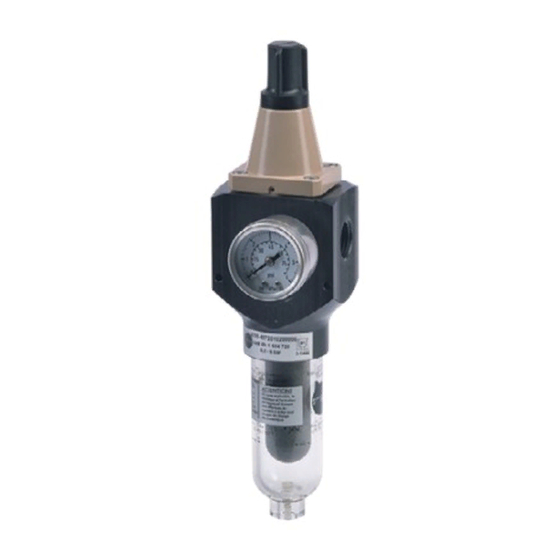
(not in view) for pressure Supply gauge or pilot valves (not in view) Output Pressure gauge Fastening bore Filter receptacle Filter cartridge Drain plug to drain off condensate Fig. 1: Components of Type 4708-45 Supply Pressure Regulator (aluminum version) EB 8546-1 EN... -
Page 7: Article Code And Versions
The supply pressure regulator is available with an aluminum or stainless steel body and a transparent plastic or metal filter receptacle. The filter cartridge installed has a mesh size of 15 µm. Supply pressure regulator Type 4708-45 Connecting thread ISO-228/1 - G ½ ½-14 NPT Set point range 0.5 to 6 bar, without pressure gauge... -
Page 8: Technical Data
Design and principle of operation 2.2 Technical data Supply pressure regulator Type 4708-45 Values measured with ½” connection Supply pressure 1 to 12 bar (15 to 180 psi) Set point range 0.2 to 1.6 bar (3 to 24 psi) or 0.5 to 6 bar (8 to 90 psi) Air consumption at 7 bar... -
Page 9: Materials
Design and principle of operation 2.3 Materials Supply pressure regulator Type 4708-45 Body Metal parts Aluminum (3.3547) or stainless steel (1.4409) Plastic parts Polyamide, glass fiber reinforced Cover Polyamide, glass fiber reinforced Polyamide, glass fiber reinforced Plug 1.4305 and polyoxymethylene Diaphragm NBR ·... -
Page 10: Mounting The Supply Pressure Regulator
Mounting the supply pressure regulator 3 Mounting the supply pressure 4 Pneumatic connections regulator The air connections (supply and output, see Fig. 1 on page 6) are designed either Î To prevent excessive amounts of con- with ISO-228/1 - G ½ or ½-14 NPT densed water from collecting, keep the threads. -
Page 11: Adjusting The Set Point
Adjusting the set point 5 Adjusting the set point 6 Maintenance Î See Fig. 1 on page 6. WARNING Î Unscrew the cap on the set point screw Risk of injury due to high pressure. and adjust the set point of the supply Shut off the air line before performing work pressure regulator. -
Page 12: Troubleshooting
Troubleshooting 7 Troubleshooting 8 Accessories/spare parts Article Order no. WARNING Filter cartridge 15 µm 8504-0068 Risk of injury due to high pressure. Filter cartridge 5 µm 8504-9040 Shut off the air line before performing work Filter receptacle, plastic 1199-0423 on the supply pressure regulator. Filter receptacle, aluminum 1199-0424 Filter receptacle, stainless steel... -
Page 13: Dimensions In Mm
Dimensions in mm 9 Dimensions in mm Type 4708-45 Supply Pressure Regulator, aluminum version Supply Output EB 8546-1 EN... - Page 14 Troubleshooting Type 4708-45 Supply Pressure Regulator, stainless steel version Supply Output EB 8546-1 EN...
- Page 16 SAMSON AG · MESS- UND REGELTECHNIK Weismüllerstraße 3 · 60314 Frankfurt am Main, Germany Phone: +49 69 4009-0 · Fax: +49 69 4009-1507 EB 8546-1 EN samson@samson.de · www.samson.de...
Need help?
Do you have a question about the 4708-45 and is the answer not in the manual?
Questions and answers