Table of Contents
Advertisement
Quick Links
Advertisement
Table of Contents

Related Manuals for Topcon UVR-T2


Summary of Contents for Topcon UVR-T2
- Page 1 INSTRUCTION MANUAL INDUSTRIAL UV CHECKER Rev.2...
-
Page 3: Introduction
Thank you so much for your purchasing our TOPCON TECHNOHOUSE Industrial UV Checker UVR- T2 series. UVR-T2 is most appropriate to manage the lamp output of the UV radiation device which is used for the following processes: sealing and adhering for electric/electronic parts, printing/drying/installing line of PCB, sterilization process in various industries, etc. - Page 4 ・ This instrument is calibrated on condition that the spectral distribution value of the calibration light source is regarded as standard. When two or more same-type detector units measure any other light source except the calibration light source, differences occur in the measured values between the units because of the dispersion in the spectral sensitivity characteristics.
-
Page 5: Display For Safe Use
DISPLAY FOR SAFE USE In order to encourage the safe use of products and prevent any danger to the operator and others or damage to existing facilities, important warnings are put on the products and inserted into the instruction manuals. We suggest that everyone understand the meaning of the following displays and icons before reading the “SAFETY PRECAUTIONS”... -
Page 6: Safety Precautions
If the instrument is heated, you may be burned. If an abnormal noise, smell or smoke comes out of this instrument, turn off the power at once. A fire will occur if using the instrument without repairing the trouble point. Consult your dealer or TOPCON TECHNOHOUSE CORPORATION. - Page 7 It may cause an electric shock. ESCAPE CLAUSES ・TOPCON TECHNOHOUSE shall not take any responsibility for damage due to fire, earthquakes, actions by the third persons and other accidents, or the negligence and misuse of the user and use under unusual conditions.
-
Page 8: Table Of Contents
CONTENTS INTRODUCTION ............................1 DISPLAY FOR SAFE USE .......................... 3 SAFETY PRECAUTIONS ........................... 4 NOTATION IN THIS MANUAL........................9 1. PREPARATIONS BEFORE USING THE INSTRUMENT ................ 10 1.1 CHECKING THE INSTRUMENT AND ACCESSORIES ..............10 1.2 NAMES OF COMPONENTS AND FUNCTIONS..................11 1.3 PREPARATION........................... - Page 9 3.2.12 Display of the instrument’s temperature..................36 4. COMMUNICATION WITH PERSONAL COMPUTER ................37 4.1 COMMUNICATION COMMAND......................37 4.2 COMMAND LIST ..........................37 4.3 COMMUNICATION PROTOCOL......................39 4.3.1 RM command ..........................39 4.3.2 LM command..........................39 4.3.3 WHO command ..........................39 4.3.4 VER command ..........................
- Page 10 6. APPENDICES ............................53 SPECIFICATIONS & PERFORMANCE ....................53 BLOCK DIAGRAM ............................ 55 APPEARANCE/DIMENSIONS ......................... 56 GRAPH ..............................59 INFORMATION ABOUT OVERSEAS REGURATION ................60...
-
Page 11: Notation In This Manual
NOTATION IN THIS MANUAL The following notation rules are used in this manual. Notation Description [MODE], [▲] Shows the switches on the keyboard and signs indicated on the liquid crystal display unit. ☞ “ ” Shows the place to which the user should refer in this manual. ☞... -
Page 12: Preparations Before Using The Instrument
1. PREPARATIONS BEFORE USING THE INSTRUMENT 1.1 CHECKING THE INSTRUMENT AND ACCESSORIES Make sure that the instrument and all the accessories are completely supplied. If any of them is missing, contact your dealer or TOPCON TECHNOHOUSE CORPORATION. Instrument ・UVR-T2 Accessories ・Quick manual... -
Page 13: Names Of Components And Functions
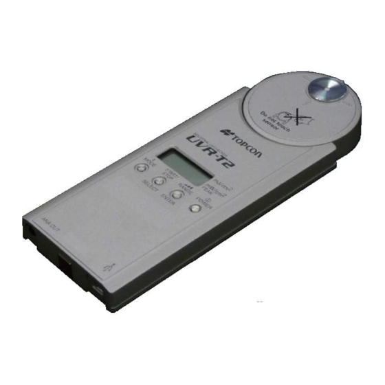
1.2 NAMES OF COMPONENTS AND FUNCTIONS ■Names of the instrument components and functions UVR-T2 Detector unit Control unit USB2.0 micro USB connector Detector window Display unit Analog output connector Battery compartment screw points Detector unit screw points Name Description Display unit This is a liquid crystal display unit which indicates the measured value, measurement conditions and other information. - Page 14 ■Names and functions of switches Mode switch Power switch Start/stop switch Range selector switch The following table shows the functions of the above switches. Switch Description [POWER] Used to turn ON/OFF the power. To turn OFF the power, press the switch for 2 seconds or more and then release it.
- Page 15 ■Names of display unit Measurement mark Indication of integral value mJ/cm² Indication of mode Integral irradiance mode: Peak irradiance mW/cm² Irradiance mode: Irradiance mW/cm² Indication of low battery Indication Description [*] This is indicated when performing measurement and zero calibration. [BAT] This is indicated when the remaining capacity of the batteries is not sufficient.
-
Page 16: Preparation
1.3 PREPARATION 1.3.1 How to mount the detector unit Do not loosen any screws except detector unit and battery compartment screw point. Push in the connector in the arrow direction. MEMO ・Be sure to turn off the power switch before connecting/disconnecting the detector unit. -
Page 17: How To Load A Battery
1.3.2 How to load a battery Install the battery to fit to the specified polarity. Leakage may occur to cause an injury or malfunction. Do not loosen any screws except detector unit and battery compartment screw point. AAA size battery for operation check do not attach at the time of shipment. Purchase those at your dealer. -
Page 18: How To Use The Analog Output Connector
1.3.3 How to use the analog output connector The analog output connector is used to output the voltage corresponding with the ultraviolet ray amount that is emitted to the detector window. The voltage output is max. 2V for each measurement range. UD-T25T2 UD-T36T2 UD-T40T2... -
Page 19: Setting Of Heatproof Cover
1.3.4 Setting of heatproof cover When measuring, set the heatproof cover. The instrument may malfunction because of heat. Don’t touch the detector window when mounting/removing the heatproof cover. If the detector window is dirty, a correct value cannot be obtained. Set the heatproof cover by sliding along the guide. -
Page 20: How To Use The Extension Cable (Optional Accessory)
1.3.5 How to use the extension cable (optional accessory) Do not loosen any screws except detector unit and battery compartment screw point. If the extension cable is used, measurement can be performed with the detector unit which is separated from the control unit. Connected to the control unit. - Page 21 Fit the connector unit in the arrow direction. 4 Tighten the screws securely to prevent the cables from coming off. 5 Set the heatproof cover exclusively for the detector unit. MEMO ・The heatproof cover for the detector unit and the extension cable are regarded as a set.
-
Page 22: How To Connect To Personal Computer
1.3.6 How to connect to personal computer When using the instrument by connecting to a personal computer, connect it to a personal computer through the accessory USB cable (cable type: “A” connector - Micro “B” connector). MEMO ・For the connection on a personal computer, refer to the manual of the personal computer being used at the same time. -
Page 23: How To Turn On/Off The Power
1.3.7 How to turn on/off the power Press the [POWER] switch to turn on the power or connect to powered-on PC with USB cable. The software version is indicated. When zero calibration at startup is valid, “CAL” is indicated on the display unit and zero calibration starts. -
Page 24: Measurement Operation
2. MEASUREMENT OPERATION 2.1 CHANGING THE MEASUREMENT MODE When startup is ended normally, “Auto▲” is indicated. Each time you press the [MODE] switch, the display of [▲][▼] is changed and the measurement mode is also changed. Integral irradiance mode Irradiance mode ■Remote measurement mode In the remote measurement mode, [▲][▼] is displayed. -
Page 25: Change Of Measurement Range
2.2 CHANGE OF MEASUREMENT RANGE When startup is ended normally, “Auto▲” is indicated. Each time you press the [RANGE] switch, the measurement range is changed with the displayed digit. “Auto” range Automatically measures with the optimal range. Range 1 It's measured in setting RANGE1, but when over range, most suitable... -
Page 26: Integral Irradiance Mode
2.3 INTEGRAL IRRADIANCE MODE When startup is ended normally, “Auto▲” is indicated. Press the [RANGE] switch to change the measurement range. When pressing the [START/STOP] switch, measurement starts. The [*] mark is indicated during measurement. The integral irradiance value is indicated during measurement. When pressing the [START/STOP] switch again, measurement stops. -
Page 27: Irradiance Mode
2.4 IRRADIANCE MODE Press the [MODE] switch to change the measurement mode. Press the [RANGE] switch to change the measurement range. When pressing the [START/STOP] switch, measurement starts. The [*] mark is indicated during measurement. The irradiance value is indicated during measurement. When pressing the [START/STOP] switch again, measurement stops. -
Page 28: Operation For A Variety Of Setting
3. OPERATION FOR A VARIETY OF SETTING 3.1 USER MODE User mode is used to change a variety of set values and check the status of the instrument. In the user mode, you can change the set values of the following twelve items and the instrument’s status. Setting automatic ON/OFF of the power Inputting the user correction factor supply... -
Page 29: Shifting/Resetting To/From User Mode
3.1.1 Shifting/resetting to/from user mode ■User mode menu Perform a variety of setting in the user mode. Shift to the user mode by the following procedure. When startup is ended normally, “Auto▲” is indicated. Press the [MODE] switch for 2 seconds or longer and then release it. Each time you press the [START/STOP] switch, the displayed menu is changed. - Page 30 ■Changing the set value/checking the display Access the user menu. Press the [START/STOP] switch to change the item to be set. Press the [RANGE] switch to shift to the setting change screen. Press the [START/STOP] switch to change the set value. To determine the changed value, press the [RANGE] switch.
-
Page 31: User Menu
3.2 USER MENU 3.2.1 Setting automatic ON/OFF of the power supply When the keys on the instrument are not operated within the set time, the instrument is automatically turned off. This setting is not applied when measurement is performed and when the remote mode is in use. The measurement represents the period that [ *... -
Page 32: Setting On/Off Of The User Zero Calibration
3.2.3 Setting ON/OFF of the user zero calibration Set ON/OFF of the user zero calibration. When OFF is set, zero calibration is performed according to the calibration data when shipped. Setting range: ON/OFF 3.2.4 Setting ON/OFF of the zero calibration at startup *This menu is displayed only when the user zero calibration is ON. -
Page 33: Execution Of Zero Calibration
3.2.5 Execution of zero calibration *This menu is displayed only when the user zero calibration is ON. Perform zero calibration manually. Press the [RANGE] switch, and the display blinks. Press the [RANGE] switch again, and zero calibration starts. Press the [MODE] switch, and blinking is ended and the original menu screen appears again. -
Page 34: Setting On/Off Of The User Correction Factor
3.2.6 Setting ON/OFF of the user correction factor Set ON/OFF of the user correction factor application. Setting range: ON/OFF 3.2.7 Input of the user correction factor *This menu is displayed only when the user correction factor is ON. Input the correction factor by which the measured value will be multiplied. How to set the correction factor •... - Page 35 Press the [RANGE] switch longer than usual, and the numeral at the highest digit blinks. Press the [RANGE] switch, and the blinking digit is shifted to the right. Each time you press the [START/STOP] switch, the value at the blinking digit is increased by “1”.
-
Page 36: Setting The Analog Output Response Speed
3.2.8 Setting the analog output response speed Set the analog output response speed. Setting range: FAST/SLOW (Response speed≤5 msec) Recommended when measuring waveforms by an ・FAST: oscilloscope and when measuring the DC light source. Recommended when measuring the AC light source and when measuring by a data ・SLOW: logger. -
Page 37: Display Of Detector Unit
3.2.10 Display of detector unit The type of the connected detector unit is displayed. T25T2 T36T2 T40T2 T3040T2 3.2.11 Display of software version The version of the instrument’s software is displayed. -
Page 38: Display Of The Instrument's Temperature
Display of the instrument’s temperature The internal temperature of the detector unit and control unit is displayed. The unit is [°C]. Detector unit temperature Control unit temperature... -
Page 39: Communication With Personal Computer
4. COMMUNICATION WITH PERSONAL COMPUTER 4.1 COMMUNICATION COMMAND This instrument can communicate with a personal computer through USB2.0. This chapter will explain the commands which will be used when the customer makes a unique program for the communication with this instrument. * Delimiter: CR: 0x0d is added to each of communication data. - Page 40 Acquires the newest error code. “_” means a space and “####” means a value. When the personal computer sends a communication command, the UVR-T2 returns “OK” as the reception check command. When the UVR-T2 receives an irrelevant command, it returns “NO”.
-
Page 41: Communication Protocol
4.3 COMMUNICATION PROTOCOL The communication protocol in USB communication (UVR-T2) is shown below. The instrument returns “OK” as the command response when receiving a command normally, “NO” when a command cannot be analyzed and “NG” when receiving normally but the processing is not normal. -
Page 42: Ver Command
4.3.4 VER command Acquires the software version. Acquisition range: 0.00 - 99.99 External control device Command UVR-T2 “VER”+CR “OK”+CR “#.##”+CR “END”+CR 4.3.5 SRL command Acquires the serial number of the control unit. Acquisition range: 00000000 - 99999999 External control device... -
Page 43: St Command
4.3.7 ST command After measurement is done once, the measurement data is returned. Command UVR-T2 External control device “ST”+CR “OK”+CR Measurement starts. ・ ・ ・ ・ ・ Measurement is ended. Measured Value + CR “END”+CR 4.3.8 CST command Starts continuous measurement. During continuous measurement, the measured value is output at regular intervals according to the average times set by the ACW command. -
Page 44: Mrw_# Command
4.3.10 MRW_# command Sets the measurement range. Setting range -1: AUTO range 1: Range 1 2: Range 2 3: Range 3 External control device Command UVR-T2 “MRW_####”+CR “OK”+CR Range change processing “END”+CR 4.3.11 MRR command Acquires the measurement range. Acquisition range -1: AUTO range 1: Range 1 2: Range 2 3: Range 3... -
Page 45: Frqr Command
4.3.13 FRQR command Acquires the measurement frequency. Acquisition range 0: 50Hz 1: 60Hz External control device Command UVR-T2 “FRQR”+CR “OK”+CR “#”+CR “END”+CR 4.3.14 TMP_# command Acquires the internal temperature of the instrument. The unit is [°C]. Setting range 0: Detector unit 1: Control unit... -
Page 46: Zcw_# Command
4.3.16 ZCW_# command Sets “Valid/Invalid” of the user zero correction. Setting range 0: Invalid 1: Valid External control device Command UVR-T2 “ZCW_#”+CR “OK”+CR Setting processing “END”+CR 4.3.17 ZCR command Acquires “Valid/Invalid” of the user zero correction. Acquisition range 0: Invalid 1: Valid... -
Page 47: Cfsw_# Command
4.3.18 CFSW_# command Sets “Valid/Invalid” of the user correction. Setting range 0: Invalid 1: Valid External control device Command UVR-T2 “CFSW_#”+CR “OK”+CR Setting processing “END”+CR 4.3.19 CFSR command Acquires “Valid/Invalid” of the user correction. Acquisition range 0: Invalid 1: Valid... -
Page 48: Cfr Command
4.3.21 CFR command Acquires the user correction factor. Acquisition range: 0.001 - 9.999 External control device Command UVR-T2 “CFR”+CR “OK”+CR “#.###”+CR “END”+CR 4.3.22 ACW_# command Sets the average times at remote measurement. Setting range: 1 - 5 External control device... -
Page 49: Apw_# Command
4.3.24 APW_# command Sets the time of “Auto power OFF”. Setting range 0: Invalid 1: 5 minutes 2: 10 minutes 3: 15 minutes 4: 30 minutes External control device Command UVR-T2 “APW”+CR “OK”+CR Setting processing “END”+CR 4.3.25 APR command Acquires the time of “Auto power OFF”. -
Page 50: Afr Command
4.3.27 AFR command Acquires the analog filter response speed. Acquisition range 0: Slow 1: Fast External control device Command UVR-T2 “AFR”+CR “OK”+CR “#”+CR “END”+CR 4.3.28 LOG command Reads out the log data saved in the internal memory when the integral irradiance measurement mode is set. -
Page 51: Output Format
4.4.1 Output format at remote measurement The output format from the instrument is shown below. Communication Format command T25T2 : UVR-T2-T25 T36T2 : UVR-T2-T36 T40T2 : UVR-T2-T40 T3040T2 : UVR-T2-T3040 #.##: Shows the software version. ########: Shows the serial number of 8 digits. -
Page 52: Usb Driver Installation
4.5 USB DRIVER INSTALLATION Install the USB driver by the following procedure. Set the CD-ROM of this software to the CD-ROM drive. Select and double-click the “dpinst.exe” file in [¥USB_DRIVER¥{os name}¥x86 or x64] folder in the CD-ROM via Explorer. For example, in the case of Windows7(32bit), it becomes [USB_DRIVER¥Windows7¥x86] For example, in the case of Windows10(64bit), it becomes [USB_DRIVER¥Windows10¥x64] The “User account control”... - Page 53 The following screen is displayed. Installation starts. When the driver installation is completed, the following screen appears. Click the [Complete] button.
-
Page 54: Error Display
5. ERROR DISPLAY 5.1 INSTRUMENT ERROR CODE This chapter will explain the error codes that are displayed on the instrument and acquired by the “ERR” command. Instrument code Code Contents Remedial measure Normal Remedial measure is not necessary. E-01 Recognition of detector Check whether the detector unit is unit has failed. -
Page 55: Appendices
6. APPENDICES SPECIFICATIONS & PERFORMANCE Specifications for each detector unit UD-T25T2 UD-T36T2 UD-T40T2 UD-T3040T2 Measurement 230 - 280nm 300 - 390nm 350 - 490nm 290 - 430nm wavelength range Peak sensitivity Approx. 255nm Approx. 355nm Approx. 410nm wavelength Irradiance display Range Limit Range... - Page 56 ・Temperature characteristics Within ±4% (in the range of 10°C to 60°C: 23°C is standard.) ・Humidity accuracy The instrument should operate normally at 85%R.H. or less. ・Analog output voltage 0 - 2Vmax (Common to each measurement range.) USB2.0 (USB A connector - USB micro B connector) ・Interface ・Power supply Alkaline AAA size dry battery: 3 pcs.
-
Page 57: Block Diagram
BLOCK DIAGRAM ■UVR-T2... -
Page 58: Appearance/Dimensions
APPEARANCE/DIMENSIONS ■UVR-T2 Instrument/Detector unit (Unit: mm) A dimension UD-T25T2 : 5mm UD-T36T2 : 3mm UD-T40T2 : 3mm UD-T3040T2:3mm Magnet Battery compartment Battery lid Slide groove (both sides) Slide groove(both sides) - Page 59 Instrument with heatproof cover...
- Page 60 Extension unit of detector unit Main body of detector unit...
-
Page 61: Graph
GRAPH Relative spectral sensitivity characteristics Oblique incident light characteristics MEMO ・The characteristics in the above graphs have been calculated from one sample of this instrument. There is some dispersion in the characteristics for each product. -
Page 62: Information About Overseas Reguration
INFORMATION ABOUT OVERSEAS REGURATION... - Page 63 One year from the date of shipment from TOPCON TECHNOHOUSE. Repair During Warranty Period If trouble should arise during normal use of the UVR-T2, we will make repairs resulting from design or manufacturing defects at no charge. Repair After Warranty Period If functionality can be restored through repair, we will repair your instrument for a charge.
- Page 64 Tel +813(3558) 2666 Fax +813(3558) 4661 ◆ Inquiries regarding repairs and maintenance Tel +813(3558) 2710 Fax +813(3558) 3011 Industrial UV Checker UVR-T2 Instruction Manual Date of Issue of 1st edition December, 2015 2nd edition March, 2017 75-1 Hasunuma-cho, Itabashi-ku, Tokyo 174-8580 Japan ©2015 TOPCON TECHNOHOUSE CORPORATION...
Need help?
Do you have a question about the UVR-T2 and is the answer not in the manual?
Questions and answers