Table of Contents
Advertisement
Advertisement
Table of Contents

Related Manuals for Topcon RT-5SW


Summary of Contents for Topcon RT-5SW
- Page 1 INSTRUCTION MANUAL ROTATING LASER RT-5SW 31380 90041...
- Page 2 TOPCON CORPORATION 75-1 Hasunuma-cho Itabashi-ku Tokyo Japan declare on our own responsibility, that the product; Kind of Product: Rotating Laser Type designation: RT-5SW/RC-300W is in compliance with the following norm(s) or documents; Radio :EN 300 328 :EN 301 489-1/17 safety :EN 60950...
-
Page 3: Foreword
Thank you for purchasing the Topcon RT-5SW Rotating Laser. It is one the world’s most advanced and accurate grade-setting lasers. To quickly and effectively use the RT-5SW, please read these brief instructions carefully, and keep them in a convenient location for future reference. -
Page 4: Safety Information
Safety Information In order to encourage the safe use of products and prevent any danger to the operator and others or damage to properties, important warnings are put on the products and inserted in the instruction manuals. We suggest that everyone understand the meaning of the following displays and icons before reading the “Safety Cautions”... -
Page 5: Safety Cautions
There is a risk of fire, electric shock or physical harm if you attempt to disassemble or repair the instrument yourself. This is only to be carried out by TOPCON or an authorized dealer,only! Laser beams can be dangerous, and can cause eye injury if used incorrectly . - Page 6 CAUTION Use of controls or adjustment or performance of procedures other than those specified herein may result in hazardous radiation exposure. Do not connect or disconnect equipment with wet hands, you are at risk of electric shocks if you do! Risk of injury by overturn the carrying case.
-
Page 7: Exceptions From Responsibility
EXCEPTIONS FROM RESPONSIBILITY 1) The user of this product is expected to follow all operating instructions and make periodic checks of the product’s performance. 2) The manufacturer, or its representatives, assumes no responsibility for results of a faulty or intentional usage or misuse including any direct, indirect, consequential damage, and loss of profits. -
Page 8: Laser Safety
User’s Guide” (IEC Publication 60825-1) provided on the safety stan?dards for laser beam. As per the said standard, this product is classified as “Class 3R Laser Products”. In case of any failure, do not disassemble the instrument. Contact TOPCON or your TOPCON dealer. -
Page 9: Table Of Contents
Contents Foreword .......................... 1 Handling Precautions....................1 Safety Information...................... 2 Safety Cautions ......................3 Laser Safety....................... 6 Contents ........................7 Standard System Components.................. 9 Nomenclature......................... 10 Sample Display......................11 Key Functions ......................12 Basic Operation......................13 Preparation and Functions ..................... 14 Power Source ...................... - Page 10 Dual axes......................... 26 How to change the rotary head speed (300, 600, 900 R.P.M.) ....... 28 Height Alert function ....................28 RT-5SW LED display....................29 Masking (Laser beam shutter) ................. 30 Change the masking mode....................31 Function Mode ....................... 33 How to set the options ..................... 37 Maintaining Power Sources ...................
-
Page 11: Standard System Components
Standard System Components 1) Instrument .........1pc. 2) Level sensor LS-70A....1pc. 3) Level sensor holder model 6 ..1pc. 4) Target .........1pc. 5) Carrying case ......1pc. 6) Instruction manual..... 1vol. 7) Battery holder DB-64C ....1pc. 8) Ni-MH battery pack BT-63Q ..1pc. 9) AC/DC converter AD-9B/7C..1pc. •... -
Page 12: Nomenclature
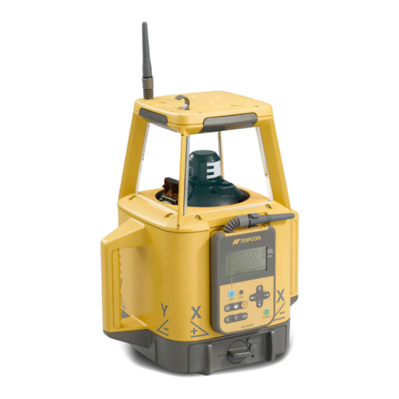
Nomenclature RC-300W Remote Controller Rotary head/Laser emitting window Beam aperture Display Escape key Handle Arrow keys Enter key Automatic alignment key Mask key XY key Power switch Function key Rotation speed key Panel / RC-300W Remote controller Battery holder Battery compartment lock DB-64C... -
Page 13: Sample Display
Mask mode Leveling (Blinks during leveling) Transmission and Channel Battery remaining reception display RT : RT-5SW Automatic alignment mark RC : RC-300W Remote controller Automatic grade setting mark Transmitting ON : Alignment is done. OFF : Alignment is not done. -
Page 14: Key Functions
Changes the rotary head speed. 300/600/900 r.p.m. Arrow keys Changes the function page / Selects the items. Inputs the grades of X Y axis. Sets the masking direction. Power switch On/Off of the RT-5SW and RC-300W. (RC-300W has auto-cut off 60 seconds function) -
Page 15: Basic Operation
Basic Operation Set the instrument on a tripod or smooth surface and power ON. If you want to use RC-300W for remote control, remove it from the instrument and power on. To precisely align the instrument, use the Automatic alignment function. See “Automatic Alignment” and “Executing Automatic alignment”... -
Page 16: Preparation And Functions
Preparation and Functions Power Source Connect the battery according to the battery type purchased. For charging and battery replacement instructions, see the “Maintaining Power sources” section. Setting Instrument Up Set the instrument on a tripod or smooth surface. The instrument must be within horizontal ±5 degrees of true level for auto-leveling to operate. -
Page 17: Rc-300W Remote Controller
When using the remote controller, raise the remote controller antenna. Operating the RC-300W The RC-300W will always operate the RT-5SW while attached to the unit. It will also operate the RT-5SW remotely when detached from the instrument. The RC-300W both sends and receives information from the RT- 5SW when it is used within 300m(984ft) of the instrument. - Page 18 RC-300W remote controller is available for number of RT-5SW. When you are using plural RT- 5SW at your job site, you can use your RC-300W for the other RT-5SW unit. Change the channel to receive the internal data of each RT-5SW to the RC-300W by operating the RC- 300W.
-
Page 19: Power Switch
When using the RC-300W for wireless remote control, also turn the instrument ON or OFF by pressing the power switch on the RC-300W. The following screen will appear if the RT-5SW did not receive the power on signal. Press the power switch again. - Page 20 If the Automatic alignment / Automatic grade setting function has been used to precisely align the grade axis, the alignment setting is maintained when the instrument is turned off. This allows you to turn off the RT-5SW to save power during non-use times without the need to re-align when the unit is turned back on.
-
Page 21: Battery Status Display
Battery status is shown in the lower bar of the remote controller display. When the remote controller is mounted to the RT-5SW, the battery status is for the RT-5SW only. When the remote controller is removed from the RT-5SW, the battery status for the remote controller is displayed. -
Page 22: Setting Grades
Setting Grades Grade can be set in both axes, X and Y, as shown below. X: –10% ~ +10% Y: –25% ~ +25% +10% +25% X axis Y axis Plus Plus Minus Minus –10% Panel side –25%... -
Page 23: How To Enter Grade
Single axis Dual axes X axis Y axis Grade range: Grade range: X: –10%~+10% X: –10%~+10% Y: –25%~+25% Y: –25%~+25% How to enter grade Press the X or Y key to begin grade input. The plus or minus symbol of the axis selected will flash. X axis Select positive or negative grade by pressing arrow keys (Up or Down). -
Page 24: Automatic Alignment
10 degrees of the true axis desired. This can be done by using the molded sights of top of the instrument housing. The RT-5SW alignment target is then positioned directly on the grade axis desired up to 150 meters (492 ft) away from the instrument. - Page 25 Using the target Hang the hook located on the rear.
-
Page 26: Executing Automatic Alignment
R. P . M target then the RC-300 POWER instrument are correctly positioned as RT-5SW precisely adjusts described in the previous section, type its grade axis to of the target, and repeat the above that location. -
Page 27: Automatic Grade Setting
Automatic grade setting range is ±5°, use the instrument within that range. Target The scanning laser locates the center of the R. P . M POWER target then the RC-300 RT-5SW precisely adjusts its grade axis to that location. Within about 150m (492ft) -
Page 28: Single Axis
Single axis Press the Auto-alignment key on the RC-300W, select [GRADE SET 1] and press the [ENT] key to finish input. Using the arrow keys, select the grade axis that is roughly aligned to the alignment target (Y+, X-, Y-, X+). Press the [ENT] key to finish input. During the grade setting, [PROCESSING ...] is displayed. - Page 29 If the tilt error of the main unit is excessive, an error may occur during the grade setting. The stability can be further improved by making an adjustment through calibration so as to minimize the error of the main unit and then using the grade setting mode. If the target tilts to left or right, an error will occur in the height from the ground to the index.
-
Page 30: How To Change The Rotary Head Speed (300, 600, 900 R
This is an optional setting that must be activated by the user. When active, the Height Alert function will not allow the RT-5SW to continue operating if the unit is disturbed after it has auto- leveled. This reminds the user that to insure accurate control, the height of the beam should re- checked after the unit has been disturbed. -
Page 31: Rt-5Sw Led Display
RT-5SW LED display (visible when RC-300W is removed) When the RC-300W is detached from the unit, a LED is visible. It provides a quick status check on the RT-5SW as follows: Yellow flashing: Auto-leveling or grade setting is in process. -
Page 32: Masking (Laser Beam Shutter)
The RT-5SW features electronic beam “masking” to prevent the beam from transmitting on one or multiple sides of the instrument. Due to the long beam range of the RT-5SW, this can be useful to eliminate duplicate laser beams on large job sites where more than one laser may be in use. -
Page 33: Change The Masking Mode
Change the masking mode Mode 1 Mode 2 Y axis As seen As seen from above from above X axis You can select a masking mode among two modes as shown above. To Set the Masking You can set the masking by pressing the Mask Key in the same manner as before. The arrow keys (Y+‚... - Page 34 Displaying selected masking mode Selected masking mode will be indicated on the main display. Mode 1 Selected masking Mode 2 mode How to select the masking mode The masking mode can be selected on page 2 of function mode. Page 2 Mask mode Mode 1 Mode 2...
-
Page 35: Function Mode
Function Mode The RT-5SW has seven function modes the user can set. 1) Laser Output Power (POWER) 2) Sensitivity Level (LEVEL) 3) Height Alert (ALERT) 4) Alarm Signal (COM) 5) Changing Masking Mode 6) Setting the target 7) Channel Setting... - Page 36 3) Height Alert Function (ALERT) When active, the Height Alert function will not allow the RT-5SW to continue operating if the unit is disturbed after it has auto-leveled. This reminds the user that to insure accurate control. (When COM is ON)
- Page 37 7) Channel Setting Set the channel of RT-5SW (only RC-300W attached to RT-5SW. In this case, the channel on the instrument and remote controller is changed.) Press the [F] key to enter Function Mode. Use the arrow key (up and down) to select the display as shown.
- Page 38 Use the arrow key (up and down) to select [SEARCH] and then press the [ENT] key. Search for the channels available on the active or standing by RT-5SW. After the search is finished, hit channels will be displayed. Use the arrow key(up and down) to position the cursor on the channel you want to select and then press the [ENT] key to establish that channel.
-
Page 39: How To Set The Options
Mask, Target, CH) by pressing the Up or Down arrow keys. After the desired item is selected, use the Page 1 Right and Left arrow keys to select the desired setting. Alarm Signal Mask Mode Setting the Target Page 2 Channel Setting of RT-5SW Page 3... - Page 40 Press the [ENT] key to set. Confirm the [OK] mark on the display. If the [NG] mark is displayed, press [ENT] again. Select and change other items by repeating the procedure.
-
Page 41: Maintaining Power Sources
RC-300W Make sure the RC-300W is off or is not active(auto cut off) before replacing its batteries. How to replace the RC-300W batteries Remove the RC-300W from the RT-5SW. Rear side Remove the battery cover from the back of the RC-300W by pressing on the cover and sliding it in the direction of the arrow. -
Page 42: Dry Battery
RT-5SW After replacing the batteries in the RT-5SW, re-attach the RC-300W once (if it was detached during battery replacement) to re-enter the status of the RT-5SW into the RC- 300W. Dry battery How to replace dry batteries Remove the battery cover by turning the battery cover knob to “OPEN”. -
Page 43: Rechargeable Battery
Red flashing : Ni-MH BT-63Q battery pack protection feature is working automatically. RT-5SW can be used in this state. Automatic protection feature; In case of overcharge or high or low temperature state exceeding charging range, charging will be stopped or changed to protect Ni-MH battery. - Page 44 1) The Ni-MH BT-63Q rechargeable battery can be charged while using the laser. 2) The Ni-MH BT-63Q rechargeable battery can be charged when the battery holder is removed from the instrument. This allows the option of alternately using two battery packs to always maintain a fully charged pack.
-
Page 45: Check And Adjusting
The Horizontal Calibration can be easily checked and, in most cases, adjustments made by the user. Both Horizontal Rotation Cone and Grade Setting can be checked by the user, but should an error be found, adjustments must be made by a Topcon service facility. Horizontal Calibration... - Page 46 [X] or [Y] key. Press the [ENT] key. (These instructions will assume the X axis was chosen.) The RT-5SW will automatically rotate internally to orient the axis selected to the staff/wall. It is not necessary to manually rotate the instrument any time during the procedure.
- Page 47 7 Press the [ENT] key on the RC-300W. The unit will Press [ENT] rotate 180 degrees internally and start auto- leveling. The RC-300W will now display “X:2”. The unit turns to 180° and starts auto- leveling. 8 When the rotary head starts rotating, do not move Note the position of the X2 laser the LS-70A laser sensor to locate the beam center.
- Page 48 (2) Adjusting Calibration 1 By pressing the UP or DOWN arrow keys on the RC-300W, move the rotating laser beam up or down as necessary until the center bar on the LS-70A display is lit. (This will be the same position as Move the X2 rotating laser until the center bar of the center of “X:1”...
- Page 49 3 Press the [ENT] key to complete the calibration. The RC-300W display will return to the axis selection screen. X: Y: If an axis remains to be checked, begin at step 4 of “Checking Calibration”. 4 To complete the calibration procedure, press the power switch to turn the instrument off.
-
Page 50: Horizontal Rotation Cone Error
6 If the difference between each set of marks is less than ±4mm (±5/32 of an inch), no error exists. If the difference between [wall A]-side and [wall B]-side exceeds ±4mm (±5/32 of an inch), contact your dealer or Topcon. -
Page 51: Grade Setting Error
Grade Setting Error Perform the following check only after completing “Horizontal Calibration” and “Horizontal Rotation Cone Error”. (1) Checking Due to the accuracy required to perform this check, the staff used in this procedure must be graduated in millimeters. 1 Securely position two nails or stakes exactly 30m (93 ft) apart. These positions will be called Nail 1 and Nail 2. - Page 52 Repeat the procedure aligning the “Y-” axis on the line created by Nail 1 and Nail 2. If the calculated result for either axis is out of the range, contact your dealer or Topcon. Example; h1 = 1370; h2 = 1390; h3 = 1362; h4 = 1080 X%=(1390-1080)-(1370-1362) X 100 = 0.010066 X 100 = 1.006%...
-
Page 53: Storage Precautions
Storage Precautions Always clean the instrument after use. Use a clean cloth, moistened with a neutral detergent or water. Never use an abrasive cleaner, ether, thinner benzene or other solvents. Always make sure instrument is completely dry before storing. Dry any moisture with a soft, clean cloth. -
Page 54: Standard / Optional Accessories
Standard / Optional Accessories Level sensor holder model 6 Level sensor holder model 5 Clamp knob Clamp knob HOLDER-6 Level sensor holder model 6 Level sensor Level sensor Level sensor holder model 5 Holder Model 5 allows the laser sensor to be moved up or down on the staff by squeezing the spring- loaded clamp on its back side without removing the sensor from the staff. - Page 55 Level sensor holder model 3 Clamp knob POWER Level sensor holder model 3 Level sensor...
- Page 56 LS-70A Laser Sensor LS-70B Laser Sensor Beam receiving window Beam receiving window Indicator Indicator Index Index Index Index Detective Detective precision switch precision switch Two leveling precision options are available, normal Two leveling precision options precision and high precision. are available, normal precision Buzzer sound Buzzer sound By pressing this switch, the...
- Page 57 The warning signal *1 and *2 will function only if RT-5SW Alert Signal function [COM] is active. See “Function Mode” section earlier in this manual. Alarm detection at the LS-70 can be canceled by turning off the LS-70, then turning it...
- Page 58 Detective Mode Replacing Battery (LS-70A/70B) HIGH NORMAL Display range 1 Press the lid in the LS-70A (LS-70A/70B) direction of the arrow to ±1mm/±.0032 ft lift. ±2mm/±.0064 ft (2mm/.0064 ft width) 2 Remove the battery and (4mm/.013 ft LS-70B width) replace with a new 9v ±1mm/±.0032 ft alkaline battery.
-
Page 59: Specifications
Specifications RT-5SW Accuracy (reproducibility) : ±5" Auto-leveling range : ±5° Measuring range (Diameter) : Approx.2 - 1200m (6 - 4000 ft) with LS-70A/B sensor Rotation speeds : 300/600/900 rpm (Changeable) Light source : L.D (Visible laser) Power supply : 4D-CELL dry batteries (DC6V) Ni-MH battery pack BT-63Q (It can be charged while using it.) - Page 60 LS-70A LS-70B Detective range : 50mm (2.0 in) Detective range : 50mm (2.0 in) Detective precision Detective precision High precision : ±1mm(±0.04 in) High precision : ±1mm(±0.04 in) Normal precision : ±2mm(±0.08 in) Normal precision : ±2mm(±0.08 in) Detective beam indication Detective beam indication Liquid crystal and buzzer Liquid crystal and buzzer...
-
Page 61: Error Display
Countermeasure Replace or recharge the batteries. RT BATT The battery of the RT-5SW is dead. If replaced, return the RC-300W to the RT-5SW after new batteries are installed. Turn the power key OFF and ON again, the auto- HI ALERT The height alert function is working. - Page 62 5SW and RC-300W in the checking and the beginning. TURN ON adjusting mode. ONLY RT Abnormality in the wireless module of the Operate the RC-300W attached to the RT-5SW. RC-300W. CONNECTION If errors still persist after attempting to clear them, contact Topcon or your dealer.
- Page 64 TOPCON CORPORATION BEIRUT OFFICE P. O. BOX 70-1002 Antelias, BEIRUT-LEBANON. TOPCON (GREAT BRITAIN)LTD. Phone: 961-4-523525/961-4-523526 Fax: 961-4-521119 Topcon House Kennet Side, Bone Lane, Newbury, Berkshire RG14 5PX U.K. TOPCON CORPORATION DUBAI OFFICE Phone: 44-1635-551120 Fax: 44-1635-551170 survey.sales@topcon.co.uk laser.sales@topcon.co.uk C/O Atlas Medical FZCO., P. O. Box 54304, C-25, Dubai Airport Free Zone,UAE...
Need help?
Do you have a question about the RT-5SW and is the answer not in the manual?
Questions and answers