
Related Manuals for Topcon GPT-7000i Series


Summary of Contents for Topcon GPT-7000i Series
- Page 1 INSTRUCTION MANUAL IMAGING TOTAL STATION GPT-7000i SERIES GPT-7001i GPT-7002i GPT-7003i GPT-7005i [STANDARD MEASUREMENT MODE]...
-
Page 3: Foreword
FOREWORD FOREWORD Thank you for purchasing the TOPCON Imaging Total Station, GPT-7000i series. For the best performance of the instruments, please carefully read these instruc- tions and keep them in a convenient location for future reference. This instruction manual explains the basic operation of this instrument. -
Page 4: General Handling Precautions
Connect the battery as soon as possible or execute RAM back-up. No responsibility TOPCON Corporation has no responsibility for loss of data stored in the memory in case unexpected accidents. Battery Cover Completely close the battery cover before using the GPT-7000i.If the battery cover is not... -
Page 5: Display For Safe Use
•There is a risk of fire, electric shock or physical harm if you attempt to disassemble or repair the instrument yourself. This is only to be carried out by TOPCON or an authorized dealer, only! •Cause eye injury or blindness. - Page 6 FOREWORD CAUTION •Do not connect or disconnect equipment with wet hands, you are at risk of electric shocks if you •Use of controls or adjustment or performance of procedures other than those specified herein may result in hazardous radiation exposure. •Let the laser beam reach the aimed object or the target without anybody else in the laser beam path.
-
Page 7: User
FOREWORD User 1)This product is for professional use only! The user is required to be a qualified surveyor or have a good knowledge of surveying, in order to understand the user and safety instructions, before operating, inspecting or adjusting. 2)Wear the required protectors (safety shoes, helmet, etc.) when operating. Exceptions from Responsibility 1)The user of this product is expected to follow all operating instructions and make periodic checks of the product’s performance. -
Page 8: Laser Safety
Equipment Classification, Requirements and User`s Guide" (IEC Publication 825) provided on the safety standard for laser beam. As per the said standard, the GPT-7000i series plumb laser type is classified as "Class 2 (II) Laser Products". In case of any failure, do not disassemble the instrument. Contact TOPCON or your TOPCON dealer. -
Page 9: Table Of Contents
FOREWORD Contents FOREWORD........... 1 General Handling Precautions . - Page 10 FOREWORD 3.3.2 Setting of the Correction for Prism Constant ....... . .55 3.3.3 Distance Measurement (Continuous Measurement) .
-
Page 11: Standard Set Composition
FOREWORD Standard Set Composition The numerical value in parentheses shows the quantity. GPT-7000i series (with lens cap) (1) Plastic carrying case(1) Stylus penÅi2) Battery charger BC-30 (1), AC-Cable (1) (For GPT-7005i) Sun shade(1) Battery BT-61Q(2) Plumb bob set(1) Tool kit with case (1) -
Page 12: Nomenclature And Functions
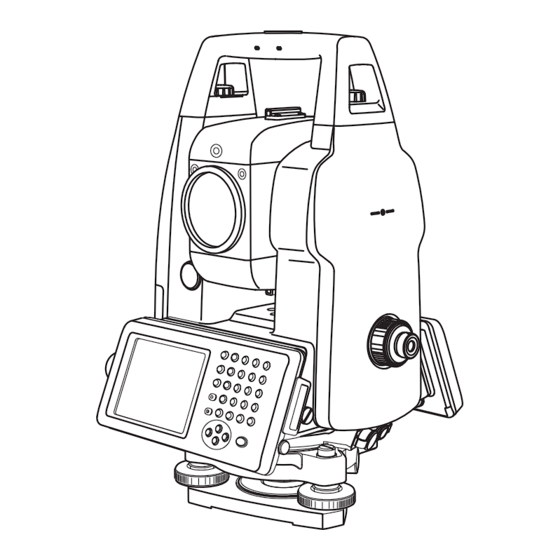
1 NOMENCLATURE AND FUNCTIONS NOMENCLATURE AND FUNCTIONS 1.1 Nomenclature Sighting collimator Carrying handle Handle fixing screw Wide sensor Objective lens, Tele sensor Laser pointer Laser aperture Instrument center mark Point guide Optical plummet telescope Display window (With touch panel) GPT-7001i GPT-7002i GPT-7003i Power supply... - Page 13 1 NOMENCLATURE AND FUNCTIONS Vertical tangent screw *1) 2speed way: GPT-7001i/7002i/7003i 1speed way: GPT-7005i Power switch Telescope focusing knob Vertical motion clamp Instrument Telescope grip center mark Card cover Hardware reset switch Telescope eyepiece (Inside the cover) Card cover lever Horizontal tangent screw 2speed way:...
-
Page 14: Display
1 NOMENCLATURE AND FUNCTIONS 1.2 Display 1.2.1 Main Menu Contains The main menu contains as following items. Select the menu by pressing icons. Display icon PROGRAM MODE ( APPLICATION MEASUREMENT) (see the instruction manual of [PROGRAM MODE]) ADJUSTMENT MODE This mode is used for checking and adjustment. ●... -
Page 15: Display Marks
1 NOMENCLATURE AND FUNCTIONS 1.2.2 Measurement Menu Example:Distance Mode V-angle: 50°10’30” H-angle: 20°30’40” Horizontal distance: 2.129m Relative elevation :1.776m Soft keys 1.2.3 Display Marks Display Contents Display Contents V-angle Meter unit Percent grade Feet unit H-angle right Fine mode H-angle left Coarse mode Horizontal distance Tracking mode... -
Page 16: Shortcut Keys
1 NOMENCLATURE AND FUNCTIONS 1.2.5 Shortcut Keys Software Reset [Shift]+[Func]+[ESC] Windows Start Menu [Ctrl]+[ESC] Continue tapping on an item Shortcut Commands [Alt]+Tap on an item Windows CE [Alt]+[TAB] Task Manager to switch to another active program or to END Task on running pro- gram(s). -
Page 17: Backlight Adjustment
1 NOMENCLATURE AND FUNCTIONS 1.3 Backlight Adjustment To conserve battery power, this instrument would automatically turn the backlight off or reduce the backlight brightness by itself when it’s not in use. In addition, the instrument can control the backlight brightness automatically by an equipped illuminometer. - Page 18 1 NOMENCLATURE AND FUNCTIONS Press the time-menu down arrow to select the reducing time. Factory setting is ‘3 minutes' as default. Press the [OK] key on title bar. After that "Power Properties" screen will close automatical l y .
-
Page 19: Adjust The Backlight Brightness By Manual
1 NOMENCLATURE AND FUNCTIONS 1.3.2 Adjust the Backlight Brightness by Manual On the "Backlight" screen, please check it 'OFF' "An illuminometer is used.”. (Factory setting is 'ON' as default) The "Brightness adjusting slide bar” will be appeared on Display. Adjust the brightness by pressing [UP-DOWN] button. Press the [OK] key on title bar. -
Page 20: Selecting The Automatic Lighting Option
1 NOMENCLATURE AND FUNCTIONS 1.3.3 Selecting the Automatic Lighting Option On the "Backlight" screen, select a Radio button from “Automatic lighting” column. (Factory setting is “The light is switched on with an illuminometer.” as default) Press the [OK] key on title bar. After that "Power Properties" screen will close automatical l y . The “Time until it switches off a backlight.”... -
Page 21: Ram Data Backup
1 NOMENCLATURE AND FUNCTIONS 1.4 RAM Data Backup If your device had not recharged during several days, the battery will be running down, and you would lose all of data on the device other than that in the "Internal Disk (internal SD card)". In addition, you might perform hardwarereset by the hardware problem or software problem. - Page 22 1 NOMENCLATURE AND FUNCTIONS Press the [YES] key. Backup function will start. Return to "RAM Backup" screen automatically, when the data back up has been completed. Press the [OK] key on title bar. After that "RAM Backup" screen will close automatically. ●...
-
Page 23: Set The Automatic Backup For Every Suspension
1 NOMENCLATURE AND FUNCTIONS 1.4.2 Set the Automatic Backup for Every Suspension On the "RAM Backup" Screen, please check it 'ON' the "RAM data will be backed up before suspension.". (Factory setting is 'ON' as default) Press the [OK] key on title bar. After that, "RAM Backup" screen will close automatically. 1.4.3 Set the Restoration Disabled after Hardware Reset On the "RAM Backup"... -
Page 24: Hardware Reset
1 NOMENCLATURE AND FUNCTIONS 1.5 Hardware Reset If your instrument not responding or an application hangs, please try to perform a software reset first. Still, when useless, please perform hardware reset. You will lose all of data on the device other than that in the "Internal Disk" after hardware reset and will need to reinstall the applications and the data you install on your instrument. -
Page 25: Touch Panel Calibration
1 NOMENCLATURE AND FUNCTIONS 1.7 Touch Panel Calibration If your instrument is not responding properly to your taps, you may need to calibrate the touch panel. ● How to calibrate the touch panel Press the icon [Start]-[Settings]-[Control Panel]- [Stylus]. You can see the "Stylus Properties" screen on Display. - Page 26 1 NOMENCLATURE AND FUNCTIONS Using the stylus pen, press the center of the targets on the screen. After pressing all targets (5 points), press the [ENT] key, or tap the display. Press the [OK] key. The display returns to previous menu.
-
Page 27: Operating Panel Key
1 NOMENCLATURE AND FUNCTIONS 1.8 Operating Panel Key To operate the keys on the screen, touch them lightly with either the accessory stylus pen or your finger. Use either the stylus pen or your finger. Do not use a ballpoint pen or a pencil. 1.8.1 Operating Key Light sensor: The stylus pen is stored beside the display. -
Page 28: Power Off
1 NOMENCLATURE AND FUNCTIONS 1.9 Power OFF When turning off the power, be sure to turn off the GPT-7000i’s power switch. ● Do not turn off the power by removing the battery. Before removing the battery, press the power switch and confirm that the power is off. Then remove the battery. -
Page 29: Function Key (Soft Key)
1 NOMENCLATURE AND FUNCTIONS 1.10 Function Key (Soft Key) The functions are according to the displayed message. Angle measuring mode (Page 1) Angle measuring mode (Page 2) Distance measuring mode (Page 1) Distance measuring mode (Page 2) Coordinate measuring mode (Page 1) Coordinate measuring mode (Page 2) - Page 30 1 NOMENCLATURE AND FUNCTIONS Angle measuring mode Page Display Function 0SET Angle of horizontal is set to 0° 00'00". HOLD Holds the horizontal angle. HSET Sets the horizontal angle by input value. The function of soft keys on next page (P2). Sets the tilt function, ON/OFF.
-
Page 31: Star Key Mode
1 NOMENCLATURE AND FUNCTIONS 1.11 Star Key Mode Press the star( ) key to view the instrument options. The following instrument options can be selected from the star key: Reticle illumination icon Point guide icon Signal level icon Laser plummet icon (Only for Laser Plummet type) Non-prism / prism switching icon Laser pointer icon... - Page 32 ● Point guide ON/OFF This feature is most useful when doing stake out work. The Point Guide's red LEDs on the GPT-7000i Series telescope assist the rod person in getting on-line. The Point Guide feature is fast and simple to use.
- Page 33 1 NOMENCLATURE AND FUNCTIONS ● Laser Plummet ON/OFF ( Only for Laser Plummet type) Laser plummet option will help you to center the instrument easily onto the measurement point. The following symbol mark will indicate that the laser is emitting. ●...
-
Page 34: Setting By Using Star Key
1 NOMENCLATURE AND FUNCTIONS 1.11.1Setting by Using Star Key [Example] : Switch on the point guide Turn the power switch on. Press the [ ] key. Press the [Point Guide] icon. The point guide will be turned on. -
Page 35: Auto Power Off
1 NOMENCLATURE AND FUNCTIONS 1.12 Auto Power Off To save battery power, the GPT-7000i would automatically turn the power off (suspend) by itself when it’s not in use. You can adjust the settings of this function. How to adjust the settings of auto power off function ●... - Page 36 1 NOMENCLATURE AND FUNCTIONS Press the [OK] key on title bar. After that "Power Properties" screen will close automatically. While on external power, the auto power off function can be enabled too. To set this function, please check it 'ON' the "Enable suspend while on external power” on the "Power Off "...
-
Page 37: Preparation For Measurement
2 PREPARATION FOR MEASUREMENT PREPARATION FOR MEASUREMENT 2.1 Power Connection (unnecessary if on-board battery BT-61Q is used) See below for connecting the external battery pack. ● Large capacity battery pack BT-3L Power cord PC-6 is used. PC-6 BT-3L PC-6... -
Page 38: Setting Instrument Up For Measurement
Mount the instrument to the tripod. Level and center the instrument precisely to insure the best performance. Use tripods with a tripod screw of 5/8 in. diameter and 11 threads per inch, such as the Type E TOPCON wide- frame wooden tripod. Reference: Leveling and Centering the Instrument 1. -
Page 39: Power Switch Key On
2 PREPARATION FOR MEASUREMENT 2.3 Power Switch Key ON Confirm the instrument is leveled. Turn the power switch ON. Progress bar will be displayed during reloading the Operating System, after you turn the instrument on at the first time or perform hardware reset. -
Page 40: Battery Power Remaining Display
2 PREPARATION FOR MEASUREMENT 2.4 Battery Power Remaining Display Battery power remaining display indicates the power condition. Battery Power Remaining Display Measurement is possible. The power is poor. The battery should be recharged or replaced with a fully charged battery. Measurement is impossible -- need to recharge or replaces the battery. -
Page 41: Vertical And Horizontal Angle Tilt Correction
2 PREPARATION FOR MEASUREMENT 2.5 Vertical and Horizontal Angle Tilt Correction When the tilt sensors are activated, automatic correction of vertical and horizontal angle for mislevelment is displayed. To ensure a precise angle measurement, tilt sensors must be turned on. The display can also be used to fine level the instrument. -
Page 42: Setting Tilt Correction By Soft Key
2 PREPARATION FOR MEASUREMENT 2.5.1 Setting Tilt Correction by Soft Key [Example] Setting Tilt OFF Press the [P1] key to get the function page 2. Press the [P2] key. Current setting is displayed. Press [OFF] key. Press [EXIT] key. The display returns previous mode. ●... -
Page 43: Compensation Of Systematic Error Of Instrument
2 PREPARATION FOR MEASUREMENT 2.6 Compensation of Systematic Error of Instrument 1) Error of vertical axis (X,Y tilt sensor offset) 2) Collimation error 3) Error of vertical angle 0 datum 4) Error of horizontal axis The above mentioned errors can be compensated by software, which calculated internally according to each compensation value. -
Page 44: How To Enter Numerals And Alphabet Letters
2 PREPARATION FOR MEASUREMENT 2.7 How to Enter Numerals and Alphabet Letters This instrument supports two ways to enter numerals and alphabet letters. One is by physical(hardware) keyboard that is similar to cellular phone method. Three alphabet characters are assigned to one numeral key. The other is by using the software input panel. - Page 45 2 PREPARATION FOR MEASUREMENT ¿ ¿ Press the [ ] key to be entering alphabet letter mode. Alphabet letter mode indicator will be appeared on the task bar. Alphabet letter mode indicator Enter Alphabets. Input 'j', Press [4](JKL)key. then the sub window featuring 'j' character will appear on the display which indicate a entering character.
- Page 46 2 PREPARATION FOR MEASUREMENT ¿ ¿ Press the [ ] key to be returning numeric mode. Alphabet letter mode indicator will be disappeared on the task bar. Input ‘104’, Press [1], [0], [4]. Then ‘104’ will be appended after ‘job_’. Press the [ENT] key.
- Page 47 2 PREPARATION FOR MEASUREMENT ● Invoke the software input panel. Press the [ ] key or press keyboard icon on the task bar and select “Keyboard” You can see the software input panel on display. You can input data as if you were typing on your PC keyboard.
-
Page 48: Data Memory Card
2 PREPARATION FOR MEASUREMENT 2.8 Data Memory Card ● How to insert a memory card Card cover Card guide Card guide Data memory Card cover card lever Push up the card cover lever to open the card cover. Insert a memory card. Make sure the card is inserted firmly in the correct direction. -
Page 49: Active Sync
2 PREPARATION FOR MEASUREMENT 2.9 Active Sync Microsoft ActiveSync is the data synchronization softwaresoftware: it synchronizes data between Windows CE devices (such as the GPT-7000i) and PCs. Using ActiveSync, the GPT-7000i can exchange data to a PC via USB cable. To establish a connection between the GPT-7000i and your PC, you first need to install ActiveSync in your PC. -
Page 50: Standard Measurement Mode
3 STANDARD MEASUREMENT MODE STANDARD MEASUREMENT MODE STANDARD MEASUREMENT MODE Angle measurement, Distance measurement, Coordinate measurement . Press the [MEAS] icon. 3.1 Screen Displays In the standard measurement mode, the collimation screen is displayed on the display device except during collimation with the telescope. The images include a telescopic image and a wide-angle image. -
Page 51: Changing The Image's Magnification
3 STANDARD MEASUREMENT MODE 3.1.2 Changing the Image's Magnification When the [ ← ] cursor key is pressed, magnification decreases. → When the [ ] cursor key is pressed, magnification increases. Displays the current magnification. There are 4 magnifications: 0.25, 0.5, 1, and 2.0. 3.1.3 Adjusting the Image's Contrast ↑... -
Page 52: Switching The Cross-Hairs On And Off
3 STANDARD MEASUREMENT MODE 3.1.4 Switching the Cross-Hairs On and Off Each time numeric key [9] is pressed, the cross-hairs appear or disappear from the image. -
Page 53: Angle Measurement
3 STANDARD MEASUREMENT MODE 3.2 Angle Measurement 3.2.1 Measuring Horizontal Angle Right and Vertical Angle Make sure the mode is in angle measurement Collimate the 1st target (A). Set horizontal angle of target (A) at 0° 00' 00". Press the [0SET] key and the [YES] key. Collimate the 2nd target (B). -
Page 54: Switching Horizontal Angle Right/Left
3 STANDARD MEASUREMENT MODE 3.2.2 Switching Horizontal Angle Right/Left Make sure the mode is angle measurement. Press the [P1] key to get the function as on page 2. Press the [R/L] key. The mode Horizontal angle Right(HR) switches to angle Left(HL) mode. Measure the target in the same manner as HR mode. -
Page 55: Measuring From The Required Horizontal Angle
3 STANDARD MEASUREMENT MODE 3.2.3 Measuring from the Required Horizontal Angle 1) Setting by Holding the Angle Make sure the mode is angle measurement. Set the required horizontal angle, using Horizontal tangent screw. Example : 20°30'40" Press the [HOLD] key . Collimate the target.*1) Press the [YES] key to finish holding the horizontal angle. -
Page 56: Vertical Angle Percent Grade(%) Mode
3 STANDARD MEASUREMENT MODE 3.2.4 Vertical Angle Percent Grade(%) Mode Make sure the mode is angle measurement. Press the [P1] key to get the function as on page 2. Press the [V/%] key. *1) *1) Every time pressing the [V/%] key, the display mode switches. -
Page 57: Distance Measurement
Setting the atmospheric correction, see Chapter 7 “SETTING ATMOSPHERIC CORRECTION” . 3.3.2 Setting of the Correction for Prism Constant Topcon's prism constant value is 0. Set correction for prism at 0. If the prism is of another manufacture, the appropriate constant shall be set beforehand. -
Page 58: Distance Measurement (Continuous Measurement)
3 STANDARD MEASUREMENT MODE 3.3.3 Distance Measurement (Continuous Measurement) Make sure the mode displays angle measurement Collimate the center of prism. Press the [ ] key. *1),*2) [Example]: Horizontal distance / Relative elevation mode The result are shown.*3) ~ *7) *1)ÅA* *1)The following characters will be shown on the 4th line right hand of the display to represent measurement mode. -
Page 59: Distance Measurement (Single/N-Times Measurement)
3 STANDARD MEASUREMENT MODE 3.3.4 Distance Measurement (Single/N-times Measurement) When presetting the number of times, the instrument measures the distance as the setting times and the average distance will be displayed. When presetting the number of times as 1 or 0, it does not display the average distance, because of single measurement. -
Page 60: Fine/ Tracking / Coarse Measuring Mode
3 STANDARD MEASUREMENT MODE 3.3.5 Fine/ Tracking / Coarse Measuring Mode •Fine mode : This is a normal distance measuring mode. Measurement time 0.2mm mode : approx.3 seconds 1 mm mode : approx.1.2 seconds The unit to be displayed is 0.2mm or 1mm. (0.001ft or 0.005ft) •Coarse mode : This mode measures in shorter time than in fine mode. - Page 61 3 STANDARD MEASUREMENT MODE Stake out operation can be performed for horizontal distance (HD), relative elevation (VD) or slope distance (SD) . [Example : Horizontal distance] Press the [P1] key in the distance measurement mode to get the function as in page 2.
-
Page 62: Coordinate Measurement
3 STANDARD MEASUREMENT MODE 3.4 Coordinate Measurement 3.4.1 Setting Coordinate Values of Occupied Point Set the coordinates of instrument (occupied point) according to coordinate origin, and the instrument automatically converts and displays the unknown point (reflector point) coordinates following the origin. Reflector (n,e,z) Inst.Point C Origin(0,0,0) - Page 63 3 STANDARD MEASUREMENT MODE Press the [N] key. Input the N coord. Press the [SET] key.*1) Press the [E] key. Input the E coord. Press the [SET] key.*1) Press the [Z] key. Input the Z coord. Press the [SET] key.*1) Press the [EXIT] key.
-
Page 64: Setting Of The Instrument Height / Reflector(Prism) Height
3 STANDARD MEASUREMENT MODE 3.4.2 Setting of the Instrument Height / Reflector(Prism) Height Measure the coordinates by entering the instrument height / reflector height, coordinates of unknown point will be measured directly. [Example] : Instrument height Confirm the angle measurement mode. Press the [ ] key. -
Page 65: Execution Of Coordinate Measuring
3 STANDARD MEASUREMENT MODE 3.4.3 Execution of Coordinate Measuring Measure the coordinates by entering the instrument height and reflector height, coordinates of unknown point will be measured directl y . ● When setting coordinate values of occupied point, see section 3.4.1“Setting Coordinate Values of Occupied Point”... -
Page 66: Data Output
3 STANDARD MEASUREMENT MODE 3.5 Data Output Result of measurement is transferred from the GPT-7000i series to Data Collector. [Example: Distance measurement mode] With the SETUP mode, set the communication parameters. Refer to Chapter 4 “PARAMETERS SETTING MODE” . After setting the communication parameters, select the distance measurement mode. -
Page 67: Data Output By [Rec] Key
3 STANDARD MEASUREMENT MODE 3.6 Data Output by [REC] Key It is also possible to output the result of measurement by pressing the [REC] key . [Example: Distance measurement mode] With the SETUP mode, set the communication parameters. Refer to Chapter 4 “PARAMETERS SETTING MODE”... -
Page 68: Parameters Setting Mode
4 PARAMETERS SETTING MODE PARAMETERS SETTING MODE PARAMETERS SETTING MODE In this mode, setting of parameters regard with measuring and communications will be done. When a parameter is changed and set, the new value is stored into the memory. 4.1 Parameter Setting Options 4.1.1 Measurement Menu Selecting Item... -
Page 69: Communication
4 PARAMETERS SETTING MODE Select the option to record the data. REC TYPE REC-A/REC-B REC-A : The measurement is started and new data is output. REC-B : The data being displayed is output. Select to record coordinates in standard or 11 digits with raw STANDARD/ NEZ REC FORM WITH RAW... -
Page 70: Setting Parameters
4 PARAMETERS SETTING MODE 4.2 Setting Parameters [Example setting] S/A BUZZER: OFF Press the [SETUP] icon. Press the [MEASUREMENT] key. Press the [NEXT] key three times. Select the [OFF] button of S/A BUZZER.*1) When the [SET] key is pressed, the setting will be set and the SETUP MODE screen will reappear. -
Page 71: Check And Adjustment
If using above procedure and no difference is found from the instrument constant at the factory or a difference of over 5mm or over (Prism mode) or 10mm or over (Non-prism mode) is found, contact TOPCON or your TOPCON dealer. -
Page 72: Checking The Optical Axis
To check if the optical axis of EDM and theodolite are matched, follow the procedure below. It is especially important to check after adjustment of the eyepiece reticle is carried out. Position a prism about 30 to 50m apart from GPT-7000i series . Press the [ADJUST] icon. Press the [EDM CHECK] key. - Page 73 5 CHECK AND ADJUSTMENT ● H direction confirmation (Do not move V direction). Turn the horizon tangent screw, move the collimating point to the left side of prism gradually until buzzer sound stops. Prism Reticle Turn the horizontal tangent screw slowly, and move the collimating point to the prism center gradually until at the position buzzer starts.
- Page 74 If the difference is within 2', no problem for use. Prism Reticle [Example] Lower side of prism 90°12'30" Upper side of prism 90°04'30" Average 90°08'30" Reading to prism center 90°08'50" Difference 20" If the difference is more than mentioned value, contact with your Topcon dealer or Topcon.
- Page 75 Repeat the previous procedure 6 to 14 in the same way in the non-prism mode. If the difference is within 2', no problem for use. If the difference is more than mentioned value, contact with your Topcon dealer or Topcon.
-
Page 76: Checking The Optical Axis Of Laser Pointer
5 CHECK AND ADJUSTMENT 5.2.2 Checking the optical axis of Laser pointer Check whether the optical axis of the laser pointer coincides with the optical axis of the telescope by carrying out the following steps. e: The laser pointer indicates the approximate collimation position of the telescope. It does not indicate the exact collimation position. - Page 77 5 CHECK AND ADJUSTMENT About30 ° The direction of the laser pointer About30 ° As seen from above Adjustment screws When screws A, B and C are turned clockwise (the direction for tightening them), the laser pointer, as seen on the target from the standpoint of the GPT-7000i, will move in the direction shown in the drawing.
-
Page 78: Checking/Adjusting The Theodolite Functions
5 CHECK AND ADJUSTMENT 5.3 Checking/Adjusting the Theodolite Functions ● Pointers on the Adjustment 1) Adjust the eyepiece of the telescope properly prior to any checking operation which involves sighting through the telescope. Remember to focus properly, with parallax completely eliminated. 2) Carry out the adjustments in the order of item numbers, as the adjustments are dependent one upon another. -
Page 79: Checking /Adjusting The Plate Level
5 CHECK AND ADJUSTMENT 5.3.1 Checking /Adjusting the Plate Level Adjustment is required if the axis of the plate level is not perpendicular to the vertical axis. ● Check 1) Place the plate level parallel to a line running through the centers of two leveling screws, say, A and B. -
Page 80: Adjustment Of The Vertical Cross-Hair
5 CHECK AND ADJUSTMENT 5.3.3 Adjustment of the Vertical Cross-hair Adjustment is required if the vertical cross-hair is not in a place perpendicular to the horizontal axis of the telescope ( since it must be possible to use any point on the hair for measuring horizontal angles or running lines). -
Page 81: Collimation Of The Instrument
5 CHECK AND ADJUSTMENT 5.3.4 Collimation of the Instrument Collimation is required to make the line of sight of the telescope perpendicular to the horizontal axis of the instrument, otherwise, it will not be possible to extend a straight line by direct means. ●... -
Page 82: Checking/Adjusting The Cross-Hairs On Telescopic/Wide-Angle Images
5 CHECK AND ADJUSTMENT First, loosen the capstan adjustment screw on the side to which the vertical cross-hair line must be moved. Then tighten the adjustment screw on the opposite side by an equal amount which will leave the tension of the adjustment screws unchanged. Revolve in the counterclockwise direction to loosen and in the clockwise direction to tighten, but revolve as little as possible. - Page 83 * In case you go beyond the adjustment range, WIDE: Wide angle a message to that effect will be displayed. In Magnification such a case, please contact TOPCON or your local Topcon dealer. Explanation of Keys [W/T] key : Switches between wide-angle and telescopic.
-
Page 84: Checking / Adjusting The Optical Plummet Telescope
5 CHECK AND ADJUSTMENT 5.3.6 Checking / Adjusting the Optical Plummet Telescope Adjustment is required to make the line of sight of the optical plummet telescope coincide with the vertical axis ( otherwise the vertical axis will not be in the true vertical when the instrument is optically plumbed). -
Page 85: Checking / Adjusting The Laser Plummet (For Laser Plummet Type)
5 CHECK AND ADJUSTMENT 5.3.7 Checking / Adjusting the Laser Plummet (For Laser Plummet type) ● Check 1) Turn on the laser plummet and coincide the center of the laser with a measuring point. 2) Rotate the instrument 180° or 200g around the vertical axis and check the measuring point. If the laser is properly centered in the measuring point, adjustment is not required. -
Page 86: Adjustment Of Vertical Angle 0 Datum
5 CHECK AND ADJUSTMENT 5.3.8 Adjustment of Vertical Angle 0 Datum If when measuring the vertical angle of target A at telescope position normal (direct) and reverse settings, the amount of normal and reverse measurements combined is other than 360° (ZENITH-0), half of the difference from 360°... -
Page 87: How To Set The Instrument Constant Value
5 CHECK AND ADJUSTMENT 5.4 How to Set the Instrument Constant Value To set the Instrument constant which is obtained in section 5.1“Checking and Adjusting of Instrument Constant” , follow as below. Press the [ADJUST] icon from the main menu. Press the [INST. -
Page 88: Compensation Systematic Error Of Instrument
5 CHECK AND ADJUSTMENT 5.5 Compensation Systematic Error of Instrument 5.5.1 Adjustment of Compensation Systematic Error of Instrument 1) Error of vertical axis (X,Y tilt sensor offset) 2) Collimation error 3) Error of vertical angle 0 datum 4) Error of horizontal axis The above mentioned errors will be compensated by software, which calculated internally according to each compensation value. - Page 89 5 CHECK AND ADJUSTMENT Turn the telescope in reverse telescope setting. Collimate target A. Press the [SET] key ten times. The number of measurements is displayed at the top right of the display. Collimate target B (more than ±10° from the level ) in reverse telescope setting.
-
Page 90: Showing Compensation Systematic Error Of Instrument
5 CHECK AND ADJUSTMENT 5.5.2 Showing Compensation Systematic Error of Instrument Press the [ADJUST] icon from the main menu. Press the [3AXIS COMPENSATION] key. Press the [CONSTANT DISPLAY] key. Press the [EXIT] key. The display returns to previous menu. -
Page 91: Setting The Prism / Non-Prism Constant Value
SETTING THE PRISM / NON-PRISM CONSTANT VALUE The prism constant value of Topcon is set to zero. When using prisms other than Topcon’s, it is necessary to set the prism constant correction value of that specific prism. Once you set the correction value for prism constant, it is retained after power is OFF. -
Page 92: Setting Atmospheric Correction
7 SETTING ATMOSPHERIC CORRECTION SETTING ATMOSPHERIC CORRECTION The velocity of light through air is not constant and depends on the atmospheric temperature and pressure. The atmospheric correction system of this instrument corrects automatically when the correction value is set. 15°C/59°F, and 1013.25hPa / 760mmHg / 29.9 inHg is as a standard value for 0ppm in this instrument. -
Page 93: Setting Of Atmospheric Correction Value
7 SETTING ATMOSPHERIC CORRECTION 7.2 Setting of Atmospheric Correction Value ● How to Set Temperature and Pressure Value Directly Measure the temperature and air pressure surrounding the instrument beforehand. ● Example : Temperature: +15°C, Pressure:1013.3 hPa Turn the power switch on. Press the [ ] key. - Page 94 7 SETTING ATMOSPHERIC CORRECTION ● How to Set the Atmospheric Correction Value Directly Measure the temperature and air pressure to find atmospheric correction value(PPM) from the chart or correction formula. Turn the power switch on. Press the [ ] key. Press the [Prism constant value, Atmospheric correction] icon.
- Page 95 7 SETTING ATMOSPHERIC CORRECTION Atmospheric Correction Chart (For your reference) The atmospheric correction value is obtained easily with the atmospheric correction chart. Find the measured temperature in horizontal, and pressure in vertical on the chart. Read the value from the diagonal line, which represents the required atmospheric correction value. Example: The measured temperature is +26°C The measured pressure is 1013 hPa...
- Page 96 7 SETTING ATMOSPHERIC CORRECTION...
- Page 97 7 SETTING ATMOSPHERIC CORRECTION...
-
Page 98: Correction For Refraction And Earth Curvature
8 CORRECTION FOR REFRACTION AND EARTH CURVATURE CORRECTION FOR REFRACTION AND EARTH CURVATURE The instrument measures distance, taking into account correction for refraction and earth curvature. 8.1 Distance Calculation Formula Distance Calculation Formula; with correction for refraction and earth curvature taken into account. Follow the Formula below for converting horizontal and vertical distances. -
Page 99: Power Source And Charging
9 POWER SOURCE AND CHARGING POWER SOURCE AND CHARGING 9.1 On-board Battery BT-61Q ● To remove Pull the battery cover lever and open the cover. Remove the battery. POWER LED CHARGE LED BT-61Q Battery cover lever AC-cable BC-30 Battery ● To charge Connect the AC-Cable to the charger. - Page 100 9 POWER SOURCE AND CHARGING ● Do not charge or discharge continuously, otherwise the battery and the charger may be deteriorated. If charging is necessary, use the charger after stopping charge for approximately 30 minutes. ● Do not charge the battery or discharge the battery in right after the battery is charged, it causes deterioration of the battery in rare cases.
-
Page 101: Detach/Attach Of Tribrach
10 DETACH/ATTACH OF TRIBRACH DETACH/ATTACH OF TRIBRACH The instrument is easily detached or attached to the tribrach, with a tribrach locking lever loosened or tightened for this purpose. ● Detachment 1) Loosen the tribrach locking lever, by revolving it 180° or 200g in the counterclockwise direction (which will point the triangle mark upwards). -
Page 102: Special Accessories
11 SPECIAL ACCESSORIES SPECIAL ACCESSORIES Battery charger BC-6 (for BT-3L) Auto converter AC-6 ● Input voltage:100, 120, 220, 240V ● Input voltage:12V DC AC: ±10% 50/60 Hz ● Output voltage :DC 8.4V ● Power consumption: 15VA approx. ● Cable length:3m approx. ●... - Page 103 11 SPECIAL ACCESSORIES Optical plummet tribrach Solar filter, Model 6 This is detachable tribrach having built-in optical A filter designed exclusively for direct collimation of the plummet telescope. sun. (Compatible with Wild) Solar filter of flap-up type. Prism unit case, Model 6 Mini prism Fixed 9 prisms unit or tilting 3 prisms unit can be The mini prism (25.4mm) is made from precision ground...
- Page 104 11 SPECIAL ACCESSORIES Prism unit case, Model 3 Back pack, Model 2 This is the plastic case to store and carry various Convenient for use in mountainous terrain. sets of prisms. The case covers one of the following prism sets: ●...
-
Page 105: Battery System
12 BATTERY SYSTEM BATTERY SYSTEM In case of On-board battery In case of External battery BT-3L PC-6 PC-5 PC-6 BT-61Q Car battery GPT-7000i series GPT-7000i series AC-6 Charging Charging time BC-30 Quick For AC100V~240V use Approx. 4h BT-61Q BC-6 Normal Approx.15h... -
Page 106: Prism System
13 PRISM SYSTEM PRISM SYSTEM Arrangement according to your needs is possible. Target pole-2 (not used with 9 prisms) Prism-2 Tilting prism Tilting prism Single prism Triple prism Tilting triple prism holder-1 9 prism holder-2 holder-3 holder-2 holder-2 holder-2 with target plate-2 Tribrach Tribrach... -
Page 107: Precautions
11) Even if any abnormality occurs, never attempt to disassemble or lubricate the instrument yourself. Always consult with TOPCON or your dealer. 12) To remove the dust on the case, never use thinner or benzine. Use a clean cloth moistened with neutral detergent. -
Page 108: Message/Error Displays
Check the procedure, then carry out been exceeded.] which the cross-hairs can be adjusted. adjustment again. ● If error still persist after attempting to clear them, contact your local Topcon dealer or Topcon head office. 15.2 Error Error code Description... -
Page 109: Specifications
16 SPECIFICATIONS SPECIFICATIONS Telescope Length : 150mm Objective lens : 45mm (EDM 50mm) Magnification : 30× Image : Erect Field of view : 1°30' Resolving power : 2.8" Minimum focus : 2.0m Reticle illumination : Provided Camera Wide-angle camera Number of effective pixels : 640 x 480 (VGA) Digital zoom magnifications : 0.25, 0.5, 1.0. - Page 110 16 SPECIFICATIONS Least Count in Measurement Fine measurement mode : 1mm (0.005ft.) / 0.2mm (0.001ft.) Coarse measurement mode : 10mm (0.02ft.) / 1mm (0.005ft.) Tracking measurement mode : 10mm (0.02ft.) Measurement Time Fine measurement mode : 1mm : Approx. 1.2sec. (Initial 3 sec.) 0.2mm : Approx.
- Page 111 : +10°C to +40°C ( +50°F to 104°F) Charging signal : Red charge lamp should glow Finishing signal : Red charge lamp should go out Weight : 0.15kg (0.3 lbs) ● Battery using time will vary depending on environmental conditions and operations done with GPT-7000i series.
-
Page 112: Appendix
17 APPENDIX APPENDIX Dual Axis Compensation Inclination of the vertical axis with respect to true vertical will result in incorrectly measured horizontal angles. The extent of the error in horizontal angle measurement due to axis tilt depends on three factors : ●... - Page 113 17 APPENDIX It is clear from the table that dual axis compensation has the most benefit when the elevation of the target is greater then 30° and the axis is tilted more than 10". The entries indicated in bold in the table show, in fact, that for many common surveying applications i.e. target elevation <30°...
-
Page 114: Index
18 INDEX INDEX ..........14 Task Manager ........ 23 Touch Panel Calibration ........... 99 TRIBRACH ...........47 Active Sync ........51 Angle Measurement ........28 Angle measuring mode ... 54 Vertical Angle Percent Grade(%) Mode ..........33 Auto Power Off ........15 Backlight Adjustment ....38 Battery Power Remaining Display ........103 BATTERY SYSTEM... - Page 115 EMC NOTICE...
- Page 116 Phone: 031-7109200 Fax: 031-7109249 TOPCON (GREAT BRITAIN)LTD. P. O. BOX 70-1002 Antelias, BEIRUT-LEBANON. Phone: 961-4-523525/961-4-523526 Fax: 961-4-521119 Topcon House Kennet Side, Bone Lane, Newbury, Berkshire RG14 5PX U.K. TOPCON CORPORATION DUBAI OFFICE Phone: 44-1635-551120 Fax: 44-1635-551170 survey.sales@topcon.co.uk laser.sales@topcon.co.uk C/O Atlas Medical FZCO., P. O. Box 54304, C-25, Dubai Airport Free Zone,UAE...
Need help?
Do you have a question about the GPT-7000i Series and is the answer not in the manual?
Questions and answers