Advertisement
Quick Links
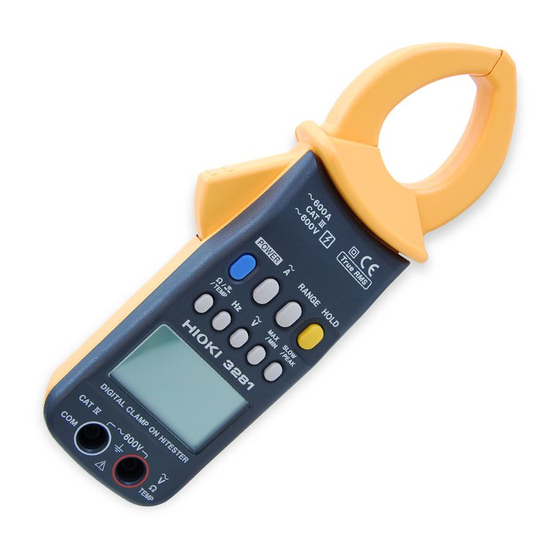
3281, 3282
DIGITAL CLAMP ON HiTESTER
Instruction Manual
Sept. 2015 Revised edition 19
Printed in Japan
3281A981-19 15-09H
Warranty
Warranty malfunctions occurring under conditions of normal use in conformity
with the Instruction Manual and Product Precautionary Markings will be
repaired free of charge. This warranty is valid for a period of one (1) year
from the date of purchase. Please contact the distributor from which you
purchased the product for further information on warranty provisions.
Introduction
Thank you for purchasing the HIOKI "HIOKI 3281, 3282 Digital Clamp-on
HiTester". To obtain maximum performance from the instrument, please read
this manual first, and keep it handy for future reference.
Inspection
When you receive the instrument, inspect it carefully to ensure that no
damage occurred during shipping. In particular, check the accessories, panel
switches, and connectors. If damage is evident, or if it fails to operate
according to the specifications, contact your dealer or Hioki representative.
Safety
This manual contains information and warnings essential for safe operation of
the instrument and for maintaining it in safe operating condition. Before
using the instrument, be sure to carefully read the following safety notes.
The following symbols in this manual indicate the relative importance of
cautions and warnings.
Indicates that incorrect operation presents an extreme hazard that
DANGER
could result in serious injury or death to the user.
Indicates that incorrect operation presents a significant hazard that
WARNING
could result in serious injury or death to the user.
Indicates that incorrect operation presents a possibility of injury to the
CAUTION
user or damage to the instrument.
Advisory items related to performance or correct operation of the
NOTE
instrument.
Safety Symbols
The
symbol printed on the instrument indicates that the user should refer
to a corresponding topic in the manual (marked with the
symbol) before
using the relevant function.
In the manual, the
symbol indicates particularly important information that
the user should read before using the instrument.
Indicates that dangerous voltage may be present at this terminal
Indicates a double-insulated device.
Indicates DC (Direct Current).
Indicates AC (Alternating Current).
Indicates a grounding terminal.
Indicates that the instrument may be connected to or disconnected from a live
circuit.
Measurement categories
This instrument conforms to the safety requirements for CAT III(3281), CAT
IV(3282) measurement instruments. To ensure safe operation of
measurement instruments, IEC 61010 establishes safety standards for
various electrical environments, categorized as CAT II to CAT IV, and called
measurement categories. These are defined as follows.
EN
CAT II: Primary electrical circuits in equipment connected to an AC electrical
outlet by a power cord (portable tools, household appliances, etc.)
CAT II covers directly measuring electrical outlet receptacles.
CAT III: Primary electrical circuits of heavy equipment (fixed installations)
connected directly to the distribution panel, and feeders from the
distribution panel to outlets.
CAT IV: The circuit from the service drop to the service entrance, and to the
power meter and primary overcurrent protection device (distribution
panel).
Using a measurement instrument in an environment designated with a
higher-numbered category than that for which the instrument is rated could
result in a severe accident, and must be carefully avoided.
Use of a measurement instrument that is not CAT-rated in CAT II to CAT IV
measurement applications could result in a severe accident, and must be
carefully avoided.
Precautions
DANGER
This instrument is designed to conform to IEC 61010 Safety Standards,
and has been thoroughly tested for safety prior to shipment. However,
mishandling during use could result in injury or death, as well as damage
to the instrument. Be certain that you understand the instructions and
precautions in the manual before use. We disclaim any responsibility for
accidents or injuries not resulting directly from instrument defects.
Do not use on the voltage
Do not use on the primary
lines exceeding 600 Vrms.
side of the breaker.
Do not input voltage in the
resistance measurement,
continuity checking and tem-
perature measurement.
WARNING
To prevent electric shock, when measuring the voltage of a power line use
a test lead that satisfies the following criteria:
Conforms to safety standards IEC61010 or EN61010
Of measurement category III or IV
Its rated voltage is higher than the voltage to be measured
The test leads provided with this instrument conform to the safety standard
EN61010.
Use a test lead in accordance with its defined measurement category and
rated voltage.
WARNING
During current measure-
Do not input voltages ex-
ment, do not connect the
ceeding 600 Vrms. (1000 V
test leads or temperature
max.)
probe to the instrument.
Avoid touching the exposed
Do not use when your
metallic parts of the jaw
hands are wet.
while measuring voltage.
Do not use the unit with the
Do not short-circuit, re-
back casing removed.
charge, disassemble or in-
cinerate batteries.
Short-circuiting
Disassembling
Be sure to insert the battery
with the polarity correct.
Battery
Handle and dispose of batteries in accordance with local regulations.
To avoid electric shock when measuring live lines, wear appropriate
protective gear, such as insulated rubber gloves, boots and a safety helmet.
Before using the instrument, make sure that the insulation on the test
leads is undamaged and that no bare conductors are improperly
exposed. Using the instrument in such conditions could cause an
electric shock. Replace the test leads and probes with the specified
Hioki Model L9207-10.
CAUTION
Do not use or store the in-
Do not subject the instru-
strument where it is exposed
ment to vibrations or
to direct sunlight, high tem-
shocks.
peratures, high humidity, or
Do not drop the instrument.
condensation.
Before using the instrument the first time, verify that it operates normally
to ensure that the no damage occurred during storage or shipping. If
you find any damage, contact your dealer or Hioki representative.
Removable sleeves are attached to the metal pins at the ends of the test
leads.
To prevent a short circuit accident, be sure to use the test leads with the
sleeves attached when performing measurements in the CAT III and
CAT IV measurement categories . In the CATII environment, if the tips
of the test leads do not reach the measurement object, remove the rigid
insulating sleeve before measuring. For details on measurement
categories, see "Measurement categories" in the instruction manual.
When performing measurements with the sleeves attached, be careful to
avoid damaging the sleeves. If the sleeves are inadvertently removed
during measurement, be especially careful in handling the test leads to
avoid electric shock.
To prevent an electric shock accident, confirm that the white or red
portion (insulation layer) inside the cable is not exposed. If a color inside
the cable is exposed, do not use the cable.
NOTE
Accurate measurement may be impossible in the presence of strong magnetic
fields, such as near transformers and high-current conductors, or in the
presence of strong electromagnetic fields such as near radio transmitters.
The
indicator lights up when the remaining battery capacity is low. In
this case, the instrument's reliability is not guaranteed. Replace the battery
immediately.
Specification
The 3281 and 3282 are different in the maximum range.(3281: 600 A, 3282: 1000 A)
1. Measurement specification
Temperature and humidity for guaranteed accuracy: 23
5
(73
or less (This is guaranteed when "
" mark is not lighting.)
Guaranteed accuracy period:1 year, or opening and closing of the jaws 10,000 times,
whichever comes first
( ) in the current ranges: 3282
Maximum rated voltage to earth: Max. 600 Vrms
Accuracy is guaranteed for over 10% input of the range in current and voltage.
Function
Mode
Range
Accuracy ( %rdg.
dgt.)
40 to 1 kHz:
30.00
1.0%rdg.
0.7%f.s.
RMS
(Effective
300.0
45 to 66 Hz:
1.0% 5
value)
600(1000)
40 to 45, 66 to 1 kHz:
1.5% 5
AC current
Auto-ranging As per the above range
(A)
30.0
40 to 1 kHz:
5% 5
PEAK
300
40 to 1 kHz:
3% 5
(Peak
600 (1000)
40 to 1 kHz:
3% 5
value)
Auto-ranging As per the above range
300.0/600
45 to 66 Hz:
1.0% 3
AC voltage
RMS
Auto-ranging
40 to 45, 66 to 1 kHz:
1.5% 3
(V)
PEAK
300/600
40 to 1 kHz:
3% 5
Crest factor
1.00 to 5.00
10% 5
30 to 99.9 Hz:
0.3% 1
Auto-ranging
Frequency (Hz)
(100.0/1000)
95 to 1000 Hz:
1% 1
Auto-ranging
Resistance (Ω)
10 to 10.00 kΩ:
1.5% 5
(1000/10.00k)
1000 Ω
Buzzer at approx. 30 Ω or less
Continuity
2. General specifications
Diameter of
3281: 33 mm dia. max. (1.3"), 3282: 46 mm dia. max. (1.8")
measurable conductor
Effect of conductor
At any position based on the center of the jaw
position
3281: Within 4.0%, 3282: Within 1.0%
Effect of external
In an external magnetic field of 400 AAC/m
magnetic field
3281: 1.5 A max., 3282: 0.2 A max.
Functions
Record (displays the maximum (MAX), minimum (MIN) and
average (AVE) values in the AC current, AC voltage and
frequency measurements), data hold (holds the display), auto-
power off (approx. 10 minutes, the buzzer alarms just before
the instrument is powered off, can be extended and released),
buzzer (can be turned on or off)
Display
LCD, digital (3000 counts), bar graph (35 segments)
Over range display: "
O.L.
" or " " (bar graph input over)
Battery consumption warning: "
" (When this mark is lighting,
the accuracy is not guaranteed.)
Data hold display: "HOLD"
Auto power-off display: "APS"
Units (A, V, Hz, Ω, kΩ,
*
,
*
)
Zero suppressor: 5 counts max.
:
Temperature probes have been discontinued.
*
The temperature measurement function is no longer available
Display update rate
Digital display: Approx. twice per second,
SLOW: Approx. once per 3 seconds,
FAST: Approx. 4 times per second
Bar graph display: approx. 4 times per second (fixed)
Response time
Current, voltage, frequency: Approx. 2.2 seconds
Resistance, continuity check: Approx. 1.1 seconds
Range selection
Auto-ranging/manual ranging (fixed range) selectable (excluding
the frequency, resistance and continuity check)
Circuit dynamic
2.5 max. (600 A (3281), 1000 A (3282), 600 V range: 1.7)
(Crest factor)
Dielectric strength
3281
Between the case and input: AC 8540 V rms /1 minute
Between the case and jaw: AC 5312 V rms /15 sec
3282
Between the case and input terminals: AC 8540 V rms /1 minute
Between the case and jaw: AC 8540 V rms /1 minute
Location for use
Altitude up to 2000 m (6562 feet), Indoors
Standards
Safety
EN 61010
applying
3281 (current): 600 VAC (Measurement Category III)
Anticipated transient overvoltage: 6000 V, Pollution Degree 2
3281 (voltage): 600 VAC (Measurement Category IV)
Anticipated transient overvoltage: 8000 V, Pollution Degree 2
3282 (current): 600 VAC (Measurement Category IV)
Anticipated transient overvoltage: 8000 V, Pollution Degree 2
3282 (voltage): 600 VAC (Measurement Category IV)
Anticipated transient overvoltage: 8000 V, Pollution Degree 2
EMC
EN 61326
Dust resistance
EN 60529 IP40
Operating
0 to 40
(32 to 104 ), 80% RH max. (no condensation)
temperature and
humidity range
Temperature
0.05 x accuracy specifications/
( ) at 0 to 40
characteristics
9 ), 80% RH
Muximum
permissible
input
3281:
600 AAC
continuous
1000 A max.
3282:
600 AAC
continuous
1000 AAC (5
minutes)
1700 A max.
600 VAC
continuous
1000 V max.
See the currents
and voltages
above
Open terminal
voltage:
3 VDC max.
Overload
protection:
600 Vrms
.
(32 to 104 )
Advertisement

Related Manuals for Hioki 3281


Summary of Contents for Hioki 3281
- Page 1 Specification WARNING This instrument conforms to the safety requirements for CAT III(3281), CAT The 3281 and 3282 are different in the maximum range.(3281: 600 A, 3282: 1000 A) IV(3282) measurement instruments. To ensure safe operation of During current measure- Do not input voltages ex- 1.
- Page 2 This function is effective for all measurement functions and modes. jaw is disconnected from the conductor. automatically (AUTO). include a detailed written description of the problem. Hioki cannot be responsible for Pressing the HOLD key again cancels HOLD display and activates the recording...
Need help?
Do you have a question about the 3281 and is the answer not in the manual?
Questions and answers