Table of Contents
Advertisement
Quick Links
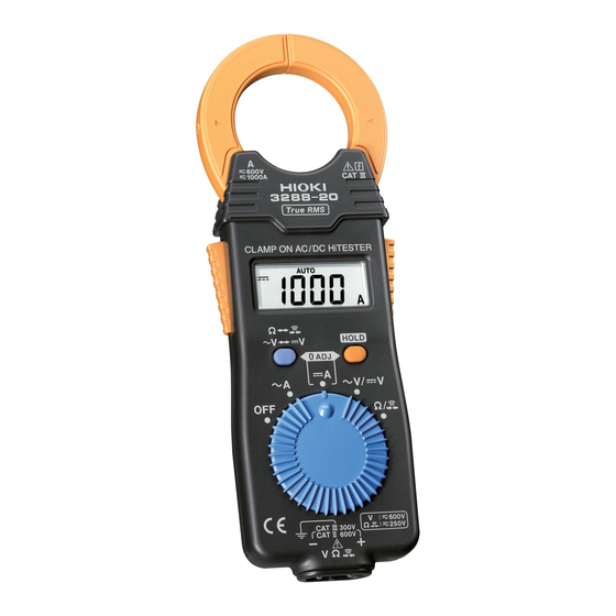
3288-20
CLAMP ON AC/DC HiTESTER
Instruction Manual
February 2015 Revised edition 6
Printed in Japan
3288C981-06 15-02H
Warranty
Warranty malfunctions occurring under conditions of normal use in conformity
with the Instruction Manual and Product Precautionary Markings will be repaired
free of charge. This warranty is valid for a period of three (3) years from the date
of purchase. Please contact the distributor from which you purchased the prod-
uct for further information on warranty provisions.
Introduction
Thank you for purchasing the HIOKI Model 3288-20 CLAMP ON AC/DC HiT-
ESTER. To obtain maximum performance from the instrument, please read this
manual first, and keep it handy for future reference.
Initial Inspection
When you receive the instrument, inspect it carefully to ensure that no damage
occurred during shipping. If damage is evident, or if it fails to operate according
to the specifications, contact your dealer or Hioki representative.
Overview
The HIOKI Model 3288-20 CLAMP ON AC/DC HiTESTER is a compact and
lightweight instrument that enables you to measure up to maximum of AC/DC
1000 A. Besides measuring current, the 3288-20 also contains DMM functions
for AC and DC voltage, resistance and continuity testing. With "True RMS" mea-
surement, it can handle measurement of distorted current waveforms. In AC cur-
rent mode it guarantees accuracy of measurement for frequency from 10 Hz.
I
Safety
This manual contains information and warnings essential for safe operation of
the instrument and for maintaining it in safe operating condition. Before using it,
be sure to carefully read the following safety precautions.
This instrument is designed to comply with IEC 61010 Safety
Standards, and has been thoroughly tested for safety prior to
shipment. However, mishandling during use could result in
injury or death, as well as damage to the instrument. Using the
instrument in a way not described in this manual may negate
the provided safety features. Be certain that you understand the
instructions and precautions in the manual before use. We dis-
claim any responsibility for accidents or injuries not resulting
directly from instrument defects.
1
Safety Symbols
In the manual, the
symbol indicates particularly important information
that the user should read before using the instrument.
The
symbol printed on the instrument indicates that the user should
refer to a corresponding topic in the manual (marked with the
before using the relevant function.
Indicates a double-insulated device.
Indicates DC (Direct Current).
Indicates AC (Alternating Current).
Indicates both DC (Direct Current) and AC (Alternating Current).
Indicates a grounding terminal.
Indicates that the instrument may be connected to or disconnected from a
live circuit.
Symbols for Various Standards
This symbol indicates that the product conforms to regulations set out by
the EC Directive.
WEEE marking:
This symbol indicates that the electrical and electronic appliance is put on
the EU market after August 13, 2005, and producers of the Member States
are required to display it on the appliance under Article 11.2 of Directive
2002/96/EC (WEEE).
The following symbols in this manual indicate the relative importance of cautions
and warnings.
Indicates that incorrect operation presents an extreme hazard that
could result in serious injury or death to the user.
Indicates that incorrect operation presents a significant hazard that
could result in serious injury or death to the user.
Indicates that incorrect operation presents a possibility of injury to the
user or damage to the device.
Indicates advisory items related to performance or correct operation of
the instrument.
Measurement categories
This instrument the current measurement section complies with CAT III 600 V safe-
ty requirements, and the voltage measurement section complies with CAT III 300
V, CAT II 600 V safety requirements. To ensure safe operation of measurement in-
struments, IEC 61010 establishes safety standards for various electrical environ-
ments, categorized as CAT II to CAT IV, and called measurement categories.
CAT II: Primary electrical circuits in equip-
ment connected to an AC electrical outlet
by a power cord (portable tools, house-
hold appliances, etc.) CAT II covers direct-
ly measuring electrical outlet receptacles.
CAT III: Primary electrical circuits of heavy
equipment (fixed installations) connected
directly to the distribution panel, and feed-
ers from the distribution panel to outlets.
CAT IV: The circuit from the service drop to the service entrance, and to the
power meter and primary overcurrent protection device (distribution panel).
Using a measurement instrument in an environment designated with a higher-
numbered category than that for which the instrument is rated could result in a
severe accident, and must be carefully avoided.
Use of a measurement instrument that is not CAT-rated in CAT II to CAT IV mea-
surement applications could result in a severe accident, and must be carefully
avoided.
Usage Notes
Follow these precautions to ensure safe operation and to obtain the full benefits
of the various functions.
Before using the instrument the first time, verify that it operates normally to en-
sure that no damage occurred during storage or shipping. If you find any dam-
age, contact your dealer or Hioki representative.
To avoid electric shock, do not touch the portion beyond the
protective barrier during use.
• Check that there is no damage to the clamp sensor, instru-
ment case before using. Do not use if there is any damage as
it could lead to electric shock.
• Before using the instrument, make sure that the insulation on
the test leads is undamaged and that no bare conductors are
improperly exposed. Using the instrument in such conditions
could cause an electric shock, so contact your dealer or Hioki
representative for repair.
• During current measurement, to avoid an electric shock acci-
dent, do not connect the test leads to the instrument.
• To avoid electric shock when measuring live lines, wear
appropriate protective gear, such as insulated rubber gloves,
boots and a safety helmet.
2
•
Be careful to avoid dropping the instrument or otherwise subjecting them to
mechanical shock, which could damage the mating surfaces of the core and
symbol)
adversely affect measurement.
• Keep the clamp jaws and core slits free from foreign objects, which could
interfere with clamping action.
Avoid the following locations that could cause an accident or damage to the instrument.
Exposed to direct sun-
light
Exposed to high tem-
perature
Exposed to liquids
Exposed to high hu-
midity or condensation
Exposed to high levels
of particulate dust
Subject to vibration
Names and Functions of Parts
Current direction indicator
Clamp sensor
Barrier
Operation grip
LCD panel
(Display: Measurement value,
Units, Symbols, Decimal point)
key
key
Function selector
Measurement
terminal
HOLD key
Plug
Test lead plug
The clamp sensor at the same side as the pushed grip
Operation grip
opens.
OFF, AC current [
A], DC current [
Function selector
age [
V/
V], Resistance and continuity test [
(Power is turned on in any position other than OFF.)
Connect the test lead plug to the measurement terminal of the
Test lead Plug
instrument for voltage measurement, resistance measurement or
Continuity Testing.
/
• For [
] function: Resistance measurement [] or Continuity
testing [
] is switchable.
key
• For [
V/
V] function: AC voltage [
key
[
V] is switchable.
• For [
A] function: Pressing this key together with HOLD key
initiates zero adjustment.
When press HOLD key,
appears in the display and the digi-
HOLD key
tal display value is maintained. Press HOLD key again to cancel
the data HOLD function.
Functions and Display
The display is blanked automatically. (Auto Power Save Function)
• The auto power save function is activated automatically when the power is
turned on. (Not possible to cancel)
• This function automatically switches to the power save state when 10 min-
utes have elapsed since the last operation. (Power save state)
• To restore from the auto power save state, turn the function selector to the
OFF position once.
The auto power save function cannot be canceled. A minute amount of power con-
tinues to flow while in the power save state. If you will not be using the tester for an
extended period of time, set the function selector to OFF or remove the battery.
Zero-adjust Function
• Before measuring DC current [
A], you must perform zero adjustment by
simultaneously pressing the
and
keys while there is no input to
HOLD
the instrument.
3
• The zero adjustment function compensates for sensor magnetization and
changes in current display over time. This function is only effective with mea-
surement of DC current [
A].
Please do not perform zero adjustment while there is any input to the instrument.
Also note that the zero-adjust function will not function when the display count is
greater than 1000.
The measurement range is automatically set to the most appro-
priate range. (Auto-range Function)
When measuring an AC current [
In the presence of corro-
DC voltage [
V], or resistance [], the measurement range is automatically
sive or explosive gases
set to the most appropriate range.
A manual range setting becomes available. (Manual Range Function)
Exposed to strong elec-
Power on the tester while holding down the
tromagnetic fields
manual range for measuring AC current [
Near electromagnetic
[
V], DC voltage [
V] or resistance []. Note that this function is not avail-
radiators
able for continuity testing. Press the
Near induction heating sys-
To switch between AC voltage [
tems. (e.g., high-frequency
the
key for at least one second.
induction heating systems
and IH cooking utensils)
Indication when the input is out of range. (Overflow indication)
When the input exceeds the measurement range, "O.F" or "-O.F" is displayed.
Specifications
Before measuring DC current [
Zero-adjust Function
zero adjustment by simultaneously pressing the
and HOLD keys.
Data hold indication
Sleeves
Power save state when 10 minutes have elapsed since
Auto power save
the last operation.
LCD panel
4199 maximum display value
Black test lead (-)
Out of range indication
O.F or -O.F
Red test lead (+)
Battery low warning
"
" is on, the measurement accuracy cannot be guaranteed.
Zero suppression
5 count or less (current measurement only)
Display update rate
400 ms ±25 ms
Range switching
Auto range / Manual range
Current range: 3 max. (1000 A range is 2 max.)
Crest factor
Voltage range: 1.5 max.
4290 V rms sine wave ( for 1 min ) between case and cir-
cuit.
7060 V rms sine wave ( for 1 min ) between clamp sensor
Dielectric strength
and case.
5400 V rms sine wave ( for 1 min ) between clamp sensor
and circuit.
Altitude up to 2000 m (6562 feet), indoors
*Battery cover (rear side)
Location for use
Pollution Degree 2
Maximum conductor diameter
35 mm (1.38") or less
for measurement
Operating temperature and
0 to 40°C (32 to 104°F), 80%RH max. (no condensation)
humidity
In 0 to 40°C range: 0.1 x Measurement accuracy /°C
Temperature characteristics
A], AC Voltage/DC Volt-
(In 32°F to 104°F range: 0.56 x Measurement accuracy /°F)
/
]
Storage temperature
-10 to 50°C (14 to 122°F), 80%RH max. (no condensation)
Power supply
CR2032 lithium battery x 1 (Rated supply voltage 3 V DC)
Maximum rated power
15 mVA
Continuous operating time
Approx. 35 hours (continuous, no load)
Dimensions
Approx. 57W x 180H x 16D mm (2.24"W x 7.09"H x 0.63"D)
Mass
Approx. 150 g (5.3 oz.)
V] or DC voltage
Accessories
Instruction Manual, L9208 Test Leads, 9398 Carrying Case
Current Measurement (ACA, DCA):
Measurement Category CAT III 600 V
(anticipated transient overvoltage 6000 V)
Maximum rated voltage to earth
Voltage Measurement (ACV, DCV):
Measurement Category CATIII 300 V, CATII 600 V
(anticipated transient overvoltage 4000 V)
Applicable standards
Safety : EN 61010, EMC: EN 61326
Accuracy
• Guaranteed accuracy period is 1 year (Opening and closing of the Clamp sen-
sor 10,000 times, whichever comes first).
• Accuracy guarantee for temperature and humidity: 23±5°C (73°F±9°F) and
80%RH or less (no condensation)
• Battery warning indicator is not lighting.
AC current measurement: true RMS value, DC current measurement: average value
Accuracy ±(%rdg.+dgt.)*
Function
Range
45 to 66 Hz
ACA
±(1.5%+5)
(
A)
100.0 A
1000 A
DCA
(
A)
Effect of conductor position: within ±2.0% (in any direction from sensor center)
A], DC current [
A], AC voltage [
V],
or HOLD key to select a
A], DC current [
A], AC voltage
key to step to the next range.
V] and DC voltage [
V], press and hold
A], you must perform
Max. input current
10 to 45, 66 to 500 Hz
1000 A rms AC
±(2.0%+5)
continuous
Figure
(See
. 1)
1000 A DC
DC ±(1.5%+5)
continuous
4
Advertisement
Table of Contents

Related Manuals for Hioki 3288-20


Summary of Contents for Hioki 3288-20
- Page 1 (fixed installations) connected directly to the distribution panel, and feed- Maximum conductor diameter Thank you for purchasing the HIOKI Model 3288-20 CLAMP ON AC/DC HiT- 35 mm (1.38") or less ers from the distribution panel to outlets. for measurement ESTER.
- Page 2 Plug the test leads into the measurement terminal. Check items Diagnose and Solution tacting your dealer or the nearest Hioki representative. When you send the unit 1. Set the function selector to / The maximum rated voltage between input terminals and...
Need help?
Do you have a question about the 3288-20 and is the answer not in the manual?
Questions and answers