Table of Contents
Advertisement
Advertisement
Table of Contents
Troubleshooting

Related Manuals for 3DHISTECH Pannoramic 1000


Summary of Contents for 3DHISTECH Pannoramic 1000
- Page 1 Pannoramic 1000 User’s Guide March 19, 2019 Rev.2...
-
Page 2: Table Of Contents
Pannoramic 1000 1.2 – User’s Guide Contents Disclaimer........................4 Declaration Of Conformity....................6 Character Formats and Symbols..................7 Notes Regarding Operational Safety................8 Notes on Warranty......................10 Terms and Abbreviations....................11 1 Product Description....................12 1.1 Product Overview........................12 1.1.1 Intended Use..............................12 1.1.2 Features and Benefits.............................13... - Page 3 Pannoramic 1000 1.2 – User’s Guide 6.3.3 Removing a slide.............................54 7 Transporting Pannoramic 1000..................56 8 Packaging instructions for Pannoramic 1000..............57 8.1 Preparations..........................57 8.2 Main parts and their accessories.....................65 8.3 Packaging..........................67 8.3.1 Packing the P1000 scanner..........................67 8.3.2 Closing the package............................70 8.3.3 Packing the accessories..........................70...
-
Page 4: Disclaimer
IP are the sole properties of the 3DHISTECH Ltd. 3DHISTECH Ltd. is not liable for damage of whatever nature (including, but not limited to, general or specific damage, indirect damage, consequential damage or incidental damage, including the... - Page 5 Pannoramic 1000 1.2 – User’s Guide Further Information For the latest information on 3DHISTECH products and services, please visit our website at the following URL: http ://www.3dhistech.com. Company Address: 3 Öv street 1141 Budapest – HUNGARY March 19, 2019 – Rev. 2 3DHISTECH Ltd.
-
Page 6: Declaration Of Conformity
Pannoramic 1000 1.2 – User’s Guide Declaration Of Conformity 3DHISTECH Ltd. declares that the product Pannoramic 1000 digital slide scanner is designed and produced with consideration of specified requirements according to the ISO13485 Medical devices. Quality management systems. Requirements for regulatory purposes (ISO 13485:2016). -
Page 7: Character Formats And Symbols
Pannoramic 1000 1.2 – User’s Guide Character Formats and Symbols Example Words or characters that appear on the screen. These include field names, screen and window titles, push-button and menu names, paths or options. Keys on the keyboard. For example, function keys (such as F11) or the Ctrl+M key combination. -
Page 8: Notes Regarding Operational Safety
The below section of this User’s Guide contains information and warnings of a kind that must be followed by owner/operator personnel. Warning and advisory symbols which are used on the base unit of the Pannoramic 1000 and in the section 1.2 Warning and Information Labels have the following meanings:... - Page 9 The front door is equipped with an interlock switch. If the door is opened while a Warning! digitization process is running, the process will be stopped instantly. A defective Pannoramic 1000 is not classified as domestic waste. It must be Warning! properly disposed in accordance with currently valid legal requirements.
-
Page 10: Notes On Warranty
Pannoramic 1000 1.2 – User’s Guide Notes on Warranty 3DHISTECH Ltd. – as the Product Manufacturer – warrants the Pannoramic 1000 to be free from faults in material and workmanship at the moment of installation. Defects must be notified immediately on identification and maximum efforts must be undertaken in order to the amount of damage as small as possible. -
Page 11: Terms And Abbreviations
Pannoramic 1000 1.2 – User’s Guide Terms and Abbreviations Comma Separated Value Field of View Numerical Aperture Virtual Slide / Slide A digital image of a thin glass plate on which specimens are mounted for microscopic study: a dynamic, interactive image that you can manage, save, magnify, zoom, name, evaluate, annotate, mark and comment, send to a colleague electronically for co- operation or advice, and so on. -
Page 12: Product Description
1.1 Product Overview 1.1.1 Intended Use Pannoramic 1000 is designed to digitize histology slides using high-numerical aperture objectives through illumination of transmitted light (Brightfield illumination). The target users of the product can work for example, in education, research, industrial, or medical sectors. -
Page 13: Features And Benefits
1.1.2 Features and Benefits 1.1.2 Features and Benefits The Pannoramic 1000 offers world-class brightfield whole slide scanning. An outstanding 0.12 µm/pixel resolution in Brightfield mode is achieved with the 40×/0.95 NA (equivalent to 80× magnification) Plan-Apochromat objective. The Pannoramic 1000 is a high-level automatic scanner with low maintenance, simple and easy use. - Page 14 Pannoramic 1000 1.2 – User’s Guide 1.1.2 Features and Benefits Different objectives are exchangeable automatically during scanning: Two dry, 20x / 40x • objectives with 40x / 80x optical equivalent magnification and 0.24 / 0.12 μm/pixel resolution Software PANNORAMIC® P1000 Scanner Control software developed for PANNORAMIC® 1000 •...
-
Page 15: Warning And Information Labels
Pannoramic 1000 1.2 – User’s Guide 1.1.3 Warning and Information Labels 1.1.3 Warning and Information Labels The following figure contains the labels used on the Pannoramic 1000 main unit. Figure 1 – Warning and information labels NOTE: The symbol refers to the possibility of exposure to biological hazards whenever handling slides. -
Page 16: Main Parts Of The Device
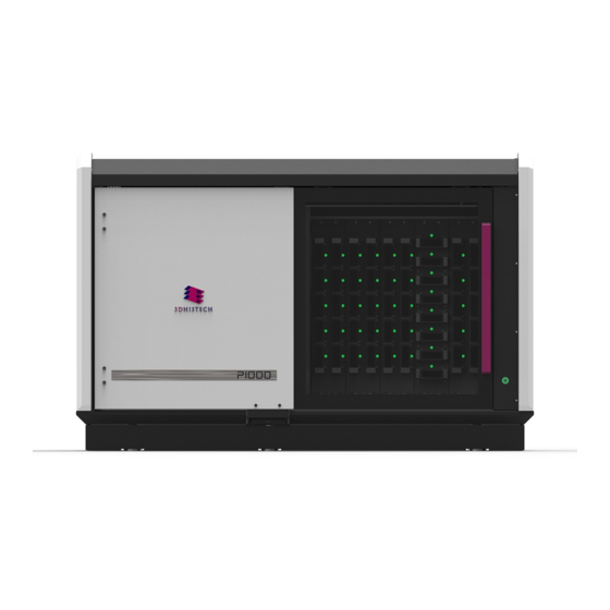
Pannoramic 1000 1.2 – User’s Guide 1.1.4 Main Parts of the Device 1.1.4 Main Parts of the Device The following figure shows the main outer parts of the base unit. Figure 2 – Main outer parts of the base unit 1. - Page 17 Pannoramic 1000 1.2 – User’s Guide 1.1.4 Main Parts of the Device The below image shows the main inner components of the base unit. Figure 3 – Main inner components of the base unit 1. Magazine compartment 2. Slide loader/grabber 3.
- Page 18 Pannoramic 1000 1.2 – User’s Guide 1.1.4 Main Parts of the Device Figure 4 – Illumination component of the Pannoramic 1000 9. PAX 10 FLASH illumination unit March 19, 2019 – Rev. 2 3DHISTECH Ltd. 18(78)
-
Page 19: Connector Panel
1.2 System Overview The standard scope of delivery of the product includes the following hardware and software items. 1.2.1 Pannoramic 1000 system The main components of the Pannoramic 1000 system are the following: 1. Pannoramic 1000 base unit 2. Monitor 3. -
Page 20: Hardware Options
Camera adapter 1.6× adapter Warning! The installation of the cameras in Pannoramic 1000 must be carried out by trained professionals! In any other case the warranty will be automatically voided. The supplier or distributor is not liable for any damages caused by an installation carried out by an unauthorized person. -
Page 21: Control Software
Pannoramic 1000 1.2 – User’s Guide 1.2.2 Hardware Options Base Unit options Pannoramic 1000 Fast Option – base unit equipped with Adimec QUARTZ Q-12A180 camera • for Brightfield scanning Objectives Plan-Apochromat 20×/NA 0.8 • Plan-Apochromat 40× Corr/NA 0.95 • Warning! Do not change correction collar settings on 40×/NA objective, if you... -
Page 22: Installation
2 Installation 2 Installation Warning! The installation of Pannoramic 1000 must be carried out by a trained professional! In any other case the warranty will be automatically voided. The supplier or distributor is not liable for any damages caused by an installation carried out by an unauthorized person. -
Page 23: Connectors And Cables
Pannoramic 1000 User’s Guide 2 Installation 1. DVD drive (RW) 2. 4x USB port 3. Audio in/out (3.5mm Jack ports) 4. Power on/off button 5. Power supply connector 6. 6x USB port 7. Network ports 8. Monitor port 9. CoaXPress Coaxlink Quad (for Adimec camera) 2.2 Connectors and cables... -
Page 24: Preparing Slides And Magazines
Pannoramic 1000 1.2 – User’s Guide 3 Preparing Slides and Magazines 3 Preparing Slides and Magazines You can use both standard and large slides and cover slips that meet the following specifications: Slides Cover slips Length 75.0 to 76.0 mm max. -
Page 25: Affixing Barcode Stickers To Slides
Pannoramic 1000 1.2 – User’s Guide 3 Preparing Slides and Magazines Caution! Do NOT scratch any circular marker onto the glass surface of a slide, use a soft tip pen instead for marking area of interest. 3.1 Affixing Barcode Stickers to Slides This section describes how to affix barcode stickers to slides. -
Page 26: Preparing Magazines
3.2 Preparing Magazines Insert slides into magazines Pannoramic 1000 features a combined magazine panel that is capable of receiving a total of 1000 slides. Pannoramic 1000 magazines are designed to receive slides of both standard and large formats. The capacity of a magazine when receiving standards slides is 20, and 5 when loading large slides, so... - Page 27 Pannoramic 1000 1.2 – User’s Guide 3.2 Preparing Magazines Figure 8 – Inserting a standard slide into a magazine Figure 9 – Inserting a large slide into a magazine Warning! Make sure that placing the magazine by reading UP SIDE at the top when inserting standard, or at the left of the magazine when inserting large slides.
- Page 28 Pannoramic 1000 1.2 – User’s Guide 3.2 Preparing Magazines Insert magazines into the device Note: Magazines can be loaded into the device once the control software has been launched. 1. If the door opener button is lit green, push the door opener button (1).
- Page 29 Pannoramic 1000 1.2 – User’s Guide 3.2 Preparing Magazines 4. Once you have inserted all the required magazines, close the door (1) by sliding it to the right. Warning! Never open the front door unless prompted accordingly by software. When you open the door at any other time, make sure not to reach with your hands into the instrument to avoid the risk of crushing your fingers.
-
Page 30: Software And Work-Flow
Pannoramic 1000 1.2 – User’s Guide 4 Software and Work-flow 4 Software and Work-flow Launch control software Run scanner software by double-clicking the icon on the desktop, and the Home View window is opened. Figure 10 – Home View The LED color of the door opener button indicates the actual status of the device: green if no process is running or has just been completed, thus the door can be opened for •... - Page 31 Pannoramic 1000 1.2 – User’s Guide 4 Software and Work-flow II. Insert magazines On how to prepare and insert magazines into the device, please read section 3. If the magazines are inserted properly, the LED above/at the side of the slot is lit in white. The status of the corresponding magazine position that is checked is indicated also in the Home View window –...
- Page 32 Pannoramic 1000 1.2 – User’s Guide 4 Software and Work-flow If connection to server is established, also the connection status and server information is displayed at the bottom left corner of the main window. Accordingly, each magazine thumbnail receives a CC stamp, to inform you that CaseCenter is selected as scanning destination.
- Page 33 Pannoramic 1000 1.2 – User’s Guide 4 Software and Work-flow After assigning a profile to a selected magazine, click or double click the profile to activate for processing. The following operation buttons are available: – Select/Deselect all – Go to Magazine View –...
- Page 34 Pannoramic 1000 1.2 – User’s Guide 4 Software and Work-flow Figure 13 – Magazine View Magazine number is displayed on the tab of the Magazine View. Slide information bar includes the following data: Figure 14 – Slide information bar 1. Status Purple –...
- Page 35 Pannoramic 1000 1.2 – User’s Guide 4 Software and Work-flow 2. Position – By double-clicking the number, the Slide View panel is opened displaying the specific slide 3. Preview status – Preview is not yet recorded ◦ – Preview image is in the queue ◦...
- Page 36 Pannoramic 1000 1.2 – User’s Guide 4 Software and Work-flow Magazine View operation buttons – Select/Deselect all – Go to Slide View – Restore modified slide attributes (name/profile) to default. – Batch preview – slides that have been scanned for preview are represented with active slide icons on the list.
- Page 37 Pannoramic 1000 1.2 – User’s Guide 4 Software and Work-flow Located at the right, there is an indicator for Brightfield mode, and the parameters set for the profile are represented with yellow icons. Figure 17 – Slide View The barcode and name of the slide are displayed over the preview image. Slide name can be edited here as well if required.
- Page 38 Pannoramic 1000 1.2 – User’s Guide 4 Software and Work-flow Preview image is taken after clicking the button. If you click the button, preview image becomes movable with the mouse and zoomable by scrolling with the mouse wheel, and FOV grid becomes more visible by zooming in, and also, the drawing toolbox is displayed.
- Page 39 Pannoramic 1000 1.2 – User’s Guide 4 Software and Work-flow Scan specimen with auto threshold – This automatically detects the specimen in the ◦ preview image. Important! Make sure that the result of detection is acceptable for you. Otherwise set the threshold value manually or append missing areas with the help of Scanned area / Preview tool function located at the preview toolbar.
- Page 40 Pannoramic 1000 1.2 – User’s Guide 4 Software and Work-flow Figure 19 – Slide View settings Remove Specks – If selected, the scanner does not digitize objects smaller than the ◦ predetermined size. This helps filtering specks and other uninteresting objects out. Set the maximum size of specks not to be digitized by adjusting the Speck size slider.
- Page 41 Pannoramic 1000 1.2 – User’s Guide 4 Software and Work-flow Preview Areas – The preview image shows the area to be digitized with a light coral colored • mask. Coverslip Area ◦ Coverslip Mode – Select Auto or Manual ▪...
- Page 42 Pannoramic 1000 1.2 – User’s Guide 4 Software and Work-flow Label Area – Modify slide label settings if necessary. Turn on Rotate 180° to rotate label by • 180 degrees. Color Correction – Different color profiles can be assigned to each slide.
- Page 43 Pannoramic 1000 1.2 – User’s Guide 4 Software and Work-flow VI. Follow-up scanning progress Progress View displays the actual progress in details. Scanning queue is listed where the performed actions can be seen. Figure 22 – Progress View with preview March 19, 2019 - Rev.
- Page 44 Pannoramic 1000 1.2 – User’s Guide 4 Software and Work-flow Scanning History View includes detailed scanning information per year / month / batch by selecting the appropriate time frame at the left side of the window. Figure 23 – Scanning history panel of Progress View...
- Page 45 Pannoramic 1000 1.2 – User’s Guide 4 Software and Work-flow Figure 24 – Scanning history panel of Progress View Workspace The actual slide status, profile, name, magazine information are automatically saved in each minute. In case of abnormal shutdown (power outage, software shutdown) when restarting the control software, upon clicking the tick mark in the pop-up window the progress status and all the user settings and data will be restored, and the scanning procedure can be continued.
-
Page 46: Using Profiles
Pannoramic 1000 1.2 – User’s Guide 5 Using Profiles 5 Using Profiles Note: Saved profile settings cannot be applied if using a different type of Pannoramic scanner. The following settings are saved in a profile: Scan Settings Grabbing method •... - Page 47 Pannoramic 1000 1.2 – User’s Guide 5 Using Profiles Label area: • Rotate by 180° degrees (ON/OFF) ◦ Color correction • Calibrated linear ◦ SRGB Standard ◦ SRGB Standard microscope-like ◦ Custom ◦ March 19, 2019 – Rev. 2 3DHISTECH Ltd.
-
Page 48: Troubleshooting And Maintenance
Pannoramic 1000 1.2 – User’s Guide 6 Troubleshooting and Maintenance 6 Troubleshooting and Maintenance 6.1 Safety Information Check cables, plugs and connections before operation, and if defective or cannot be replaced, contact 3DHISTECH Service for support. Check whether the device is compatible with your local line voltage. It can operate at line voltages 100V to 240V and 50/60 Hz. -
Page 49: Cleaning The Condenser
Pannoramic 1000 1.2 – User’s Guide 6.1.2 Cleaning the condenser 6.1.2 Cleaning the condenser Warning! Before cleaning, switch off the device and pull the power cord out of the connector. Figure 25 – Condenser unit 1. Open service door. 2. Gently move the slide holder (2) into the middle above the condenser (1). -
Page 50: Preventive Maintenance
Pannoramic 1000 1.2 – User’s Guide 6.1.3 Preventive maintenance 6.1.3 Preventive maintenance To prevent fungus growth Do not leave the equipment in an unconditioned environment with a storage temperature • above 60°C (140°F) or below 0°C (32°F), which may damage the equipment. - Page 51 Pannoramic 1000 1.2 – User’s Guide 6.2 Troubleshooting Virtual slides show poor stitching in Viewer Scan camera not properly adjusted (for example, due to loose fixture) • Contact 3DHISTECH Service for support. • Slide is often positioned incorrectly Guiding fault in transport system •...
-
Page 52: Maintenance
For maintenance solutions not described in this manual, contact the service personnel. 6.3.1 Removing the protective cover To perform any maintenance work on the device, the protective cover of the Pannoramic 1000 is needed to be removed. Caution! -
Page 53: Replacing Fuses Of The Main Power Switch
Pannoramic 1000 1.2 – User’s Guide 6.3.2 Replacing fuses of the main power switch 6.3.2 Replacing fuses of the main power switch 1. Switch off the main power supply and disconnect the power supply cable (see section 1.1.4 Base Unit). -
Page 54: Removing A Slide
Pannoramic 1000 1.2 – User’s Guide 6.3.3 Removing a slide 6.3.3 Removing a slide If a slide got jammed, fell down from the arm of the grabber or has suffered breakage during the process of digitization, stop the process and, if possible, move the slide holder/grabber to a position where the slide can be easily removed. - Page 55 Pannoramic 1000 1.2 – User’s Guide 6.3.3 Removing a slide 5. Close the door(s). 6. Connect the power cable of the power supply to the power outlet and switch on the power supply. 7. Launch control software. March 19, 2019 – Rev. 2 3DHISTECH Ltd.
-
Page 56: Transporting Pannoramic 1000
Pannoramic 1000 1.2 – User’s Guide 7 Transporting Pannoramic 1000 7 Transporting Pannoramic 1000 The below sequence of steps demonstrate how to move Pannoramic 1000 to another location within a building: Caution! The base unit does not have carrying handles for transporting. At least 4 or 6 persons can carry the base unit by holding it by its base plate. -
Page 57: Packaging Instructions For Pannoramic 1000
Pannoramic 1000 1.2 - User’s Guide 8 Packaging instructions for Pannoramic 1000 8 Packaging instructions for Pannoramic 1000 8.1 Preparations 1. Unload slides (if there is any) from the slide holder unit by using the scanner software. 2. Close the scanner software normally. - Page 58 Pannoramic 1000 1.2 - User’s Guide 8 Packaging instructions for Pannoramic 1000 (b) Objective changer Mount the transport fix (A) for the objectives (B) to the upper horizontal plate of the microscope (C) with 2 pcs of M5x25 socket head cap screw (D). Use a 4 mm hexagon wrench tool.
- Page 59 Pannoramic 1000 1.2 - User’s Guide 8 Packaging instructions for Pannoramic 1000 Figure 34 – Mount fixing blocks on objective changer Figure 35 – Mount fixing blocks on objective changer 3DHISTECH Ltd. March 19, 2019 - Rev. 2 59(78)
- Page 60 Pannoramic 1000 1.2 - User’s Guide 8 Packaging instructions for Pannoramic 1000 Mount the focus unit (A) with M3 spacers (B) and M3x16 socket head cap screws (C). Use a 2,5 mm hexagon wrench tool. (Figure 36-37) Figure 36 – Mount focus unit Figure 37 –...
- Page 61 Pannoramic 1000 1.2 - User’s Guide 8 Packaging instructions for Pannoramic 1000 (c) X-Y stage, slide holder The stage should be in the transport position. Mount the transport fix (A) (shaped like a bridge) above the stage with M5x30 socket head cap screws (B).
- Page 62 Pannoramic 1000 1.2 - User’s Guide 8 Packaging instructions for Pannoramic 1000 Figure 40 – Mount fixing to stage Figure 41 – Mount fixing to stage Figure 42 – Mount fixing to stage 3DHISTECH Ltd. March 19, 2019 - Rev. 2...
- Page 63 Pannoramic 1000 1.2 - User’s Guide 8 Packaging instructions for Pannoramic 1000 II. Slide loading unit (a) X-Y (horizontal/vertical) movement Move the X-Y slide loading unit (contains also the gripper unit) (B+C) by hand to the transport position (to the bottom right hand corner).
- Page 64 Pannoramic 1000 1.2 - User’s Guide 8 Packaging instructions for Pannoramic 1000 (b) Gripper unit (slide in-out) Bind the tooth belt fixing (A) to the stepper motor (B) with a red strap (C). (Figure 45) Figure 45 – Mount fixing strap on tooth belt III.
-
Page 65: Main Parts And Their Accessories
Pannoramic 1000 1.2 - User’s Guide 8 Packaging instructions for Pannoramic 1000 4. Take off the rocker panels (if any) from the sides and from the front. Just pull them outward. They are mounted/hold by magnets. 5. Turn off and disconnect all the cables of the workstation and display. - Page 66 Pannoramic 1000 1.2 - User’s Guide 8 Packaging instructions for Pannoramic 1000 2. BOX 2 – Accessories a) power supply cable b) magazines for P1000 c) 3DH SW box d) install disc (in SW box) e) dongles 3. BOX 3 – Carton box dedicated for the PC...
-
Page 67: Packaging
Pannoramic 1000 1.2 - User’s Guide 8 Packaging instructions for Pannoramic 1000 8.3 Packaging The scanner is packed in a huge wooden box. The computer and monitor have separate boxes (as seen above). Detailed images of the wood box can be found at the end of this document. - Page 68 Pannoramic 1000 1.2 - User’s Guide 8 Packaging instructions for Pannoramic 1000 Figure 49 – BOX 1 Figure 50 – BOX 1 Please take Side B to its place on the right. The foams should fill the ~50 mm gap. Use the latches to fix the side wood panel.
- Page 69 Pannoramic 1000 1.2 - User’s Guide 8 Packaging instructions for Pannoramic 1000 Figure 51 – BOX 1 Put the foams for the transport plates on the top of the rocker panels’ foams. Place in the transport plates. (Figure 52) Figure 52 – BOX 1 Stand the other side wood panels on the basement one at a time then fix them with the draw latches.
-
Page 70: Closing The Package
Pannoramic 1000 1.2 - User’s Guide 8 Packaging instructions for Pannoramic 1000 8.3.2 Closing the package Place the top panel to BOX 1. Secure it with the latches. 8.3.3 Packing the accessories Place inside computer and its accessories into BOX 2 and display and cables into BOX 3. Secure them with straps. - Page 71 Pannoramic 1000 1.2 - User’s Guide 8 Packaging instructions for Pannoramic 1000 Figure 53 – Box labeling Package must be stored and transported between the temperature and humidity rates on Figure 54. Figure 54 – Transportation- and storage-related labeling 3DHISTECH Ltd.
-
Page 72: Construction Of The Wooden Box
Pannoramic 1000 1.2 - User’s Guide 8 Packaging instructions for Pannoramic 1000 8.5 Construction of the wooden box Figure 55 – Construction of the wooden box 1. Base 2. Side A 3. Side D 3DHISTECH Ltd. March 19, 2019 - Rev. 2... - Page 73 Pannoramic 1000 1.2 - User’s Guide 8 Packaging instructions for Pannoramic 1000 4. Side B 5. Top of BOX 1 6. Foam for fixing the scanner - G 7. Foam for fixing the scanner – C 8. Foam for fixing the scanner – E 9.
- Page 74 Pannoramic 1000 1.2 - User’s Guide 8 Packaging instructions for Pannoramic 1000 Figure 57 – Construction of the wooden box 3DHISTECH Ltd. March 19, 2019 - Rev. 2 74(78)
-
Page 75: Technical Data
Pannoramic 1000 1.2 – User’s Guide 9 Technical Data 9 Technical Data Dimensions (width x depth x height) Base unit Approx. 1540 x 902 x 1004 mm Weight Base unit Approx. 270 kg Ambient conditions Transportation / shipment (packed) Permissible ambient temperature -40°C to +70°C... - Page 76 Pannoramic 1000 1.2 – User’s Guide 9 Technical Data Operating data Intended site closed room facilities Electrical protection class Internal protection degree IP 20 Electrical safety in compliance with EN61010-1:2010, EN61010-2-081:2015, EN61010-2-101:2017 Over-voltage category Electromagnetic compatibility in compliance with EN61326-2-6:2013...
- Page 77 Pannoramic 1000 1.2 – User’s Guide 9 Technical Data Control computer, minimum system requirements Operating System Microsoft Windows 10 64-bit EN Intel Xeon Gold 5120 14C 2.2 GHz 12x8 GB DDR4-2666 rg ECC Hard disk 1+2 TB Optical drive DVD SuperMulti SATA slim...
-
Page 78: Index
Brightfield........................13, 20, 21, 76 CaseCenter............................21 Control software........................12, 21, 54 Focus..............................50 Marker............................39, 46 Pannoramic 1000............8, 9, 10, 12, 13, 15, 19, 20, 21, 22, 26, 52, 56 Pannoramic Viewer...........................21 Preview...........................23, 26, 39, 41 Scan.......................13, 39, 40, 41, 46, 51, 76 Scanner.............................40 March 19, 2019 –...
Need help?
Do you have a question about the Pannoramic 1000 and is the answer not in the manual?
Questions and answers