Table of Contents
Advertisement
Quick Links
Advertisement
Table of Contents

Related Manuals for IFM Electronic SA 00 Series


Summary of Contents for IFM Electronic SA 00 Series
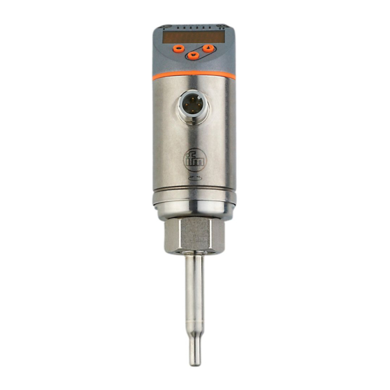
- Page 1 Operating instructions Flow sensor SAxx00 SAxx10 SAxx30 SAxx40...
-
Page 2: Table Of Contents
Contents 1 Preliminary note ���������������������������������������������������������������������������������������������������4 2 Safety instructions �����������������������������������������������������������������������������������������������4 3 Functions and features ����������������������������������������������������������������������������������������5 4 Function ���������������������������������������������������������������������������������������������������������������5 4�1 Operating modes (ModE) ������������������������������������������������������������������������������6 4�2 Select the medium (MEdI) �����������������������������������������������������������������������������6 4�3 Define the internal pipe diameter (diA) ����������������������������������������������������������6 4�4 Customer-specific calibration (CGA) �������������������������������������������������������������7 4�5 Switching function ������������������������������������������������������������������������������������������8 4�6 Analogue function ������������������������������������������������������������������������������������������9 4�7 Frequency output �����������������������������������������������������������������������������������������... - Page 3 10�1�4 Timeout ���������������������������������������������������������������������������������������������29 10�2 Settings for volumetric flow monitoring ������������������������������������������������������30 10�2�1 Define the operating mode ���������������������������������������������������������������30 10�2�2 Define the internal pipe diameter ������������������������������������������������������30 10�2�3 Configure the limit value monitoring for flow for OUT1 ���������������������31 10�2�4 Configure the limit value monitoring for flow for OUT2 ���������������������31 10�2�5 Configure the frequency signal for flow for OUT1 ����������������������������31 10�2�6 Configure the frequency signal for flow for OUT2 ����������������������������31 10�2�7 Configure the analogue output for flow for OUT2 �����������������������������32...
-
Page 4: Preliminary Note
1 Preliminary note Technical data, approvals, accessories and further information at www�ifm�com� ► Instructions > Reaction, result […] Designation of keys, buttons or indications → Cross-reference Important note Non-compliance may result in malfunction or interference� Information Supplementary note� CAUTION Warning of personal injury� Slight reversible injuries may result�... -
Page 5: Functions And Features
3 Functions and features The unit monitors liquids and gases� It detects the process categories flow and medium temperature� Application area • Air • Water • Glycol solutions (reference medium: 35 % ethylene glycol solution) • Low-viscosity oils (viscosity: ≤ 40 mm²/s at 40 °C / ≤ 40 cSt at 104 °F) •... -
Page 6: 4�1 Operating Modes (Mode)
4.1 Operating modes (ModE) The unit provides three selectable operating modes for flow measurement: Operating Medium Display unit mode Liquids, air % (of the taught range) → 10.2.8 LIQU Liquids m/s, l/min, m3/h (fps, gpm, cfm) m/s, l/min, m3/h (fps, gpm, cfm) The selected operating mode has no effect on the temperature measure- ment, only absolute values in °C or °F are indicated. -
Page 7: 4�4 Customer-Specific Calibration (Cga)
4.4 Customer-specific calibration (CGA) Via the calibration factor CGA the sensor can be adjusted to a reference flow in the application� The customer-specific calibration allows changing the gradient of the curve of measured values� It influences the display and the outputs� A = Operating value for display and 140 % MEW output signals... -
Page 8: 4�5 Switching Function
4.5 Switching function OUTx changes its switching status if it is above or below the set switching limits (flow or temperature)� Hysteresis or window function can be selected� Example of flow monitoring: Hysteresis function Window function SP = set point FH = upper limit value rP = reset point FL = lower limit value... -
Page 9: 4�6 Analogue Function
4.6 Analogue function The unit provides an analogue signal that is proportional to the flow quantity or the medium temperature� Within the measuring range the analogue signal is 4���20 mA� The measuring range is scalable: • [ASP2] determines at which measured value the output signal is 4 mA� •... - Page 10 [mA] FOU=On 21,5 FOU=OFF [% MEW] Figure 1: Characteristics of the analogue output according to the standard IEC 60947-5-7� Volumetric flow Medium temperature MAW: Initial value of the measuring range for non-scaled measuring range MEW: Final value of the measuring range for non-scaled measuring range ASP: Analogue start point with scaled measuring range AEP: Analogue end point with scaled measuring range Below the display range...
-
Page 11: 4�7 Frequency Output
4.7 Frequency output The unit provides a frequency signal that is proportional to the volumetric flow and the medium temperature� Within the measuring range the frequency signal is between 0 and 100 Hz for the factory setting� The frequency signal is scalable: •... -
Page 12: 4�8 Measured Value Damping (Dap)
Flow measurement Temperature monitoring FOU=On FOU=On 130 % 130 % 120 % 120 % =100 % =100 % FOU=OFF FOU=OFF OL Err OL Err 100 % 120 % 100 % 120 % Figure 2: Output curve frequency output MAW: Initial value of the measuring range for non-scaled measuring range MEW: Final value of the measuring range for non-scaled measuring range FSP: Frequency start point with scaled measuring range (only temperature) FEP: Frequency end point with scaled measuring range... -
Page 13: 4�9 Colour Change Display (Colr)
4.9 Colour change display (coLr) The colour of the characters in the display can be set via the parameter [coLr] (→ 10.4.4)� With the set parameters rED (red) and GrEn (green), the display is permanently set to one colour� If the parameters rxou and Gxou are set, the colour of the characters changes depending on the process value: OUT1 OUT2... -
Page 14: 4�10�1 Io-Link Process Values
The IODDs necessary for the configuration of the unit, detailed information about process data structure, diagnostic information, parameter addresses and the necessary information about the required IO-Link hardware and software can be found at www�ifm�com� 4.10.1 IO-Link process values The process values for flow and temperature are transmitted via IO-Link in the following units of measurement: Operating mode Unit of the transmitted process values... -
Page 15: 5�1 Installation Position
• A correct fit of the unit and ingress resistance of the connection are only en- sured using ifm adapters� ► Observe the instructions of the mounting accessories� ► Use a lubricating paste which is suitable and approved for the applica- tion�... - Page 16 Recommended For horizontal pipes: mounting from the For vertical pipes: side� mounting in the rising pipe� Conditionally possible Horizontal pipe /mounting from the bottom: Horizontal pipe /mounting from the top: if if the pipe is free from build-up� the pipe is completely filled with medium�...
-
Page 17: 5�2 Interference In The Pipe System
Not allowed The sensor tip must not be in contact with Do not mount in downpipes that are open the pipe wall� at the bottom� 5.2 Interference in the pipe system Components integrated in the pipes, bends, valves, reductions, etc� lead to turbu- lence of the medium�... -
Page 18: 5�3 Alignment
5.3 Alignment ► To achieve the optimum measuring accuracy: mount the sensor in a way that the flow goes to the larger of the two key surfaces (1)� On units with an external thread, a bore hole in the key surface (2) indi- cates the flow direction�... - Page 19 BK: black BN: brown OUT2 BU: blue OUT1 WH: white Colours to DIN EN 60947-5-2 Sample circuits: 2 x positive switching 2 x negative switching 1 BN 1 BN 2 WH 2 WH 4 BK 4 BK 3 BU 3 BU 1 x positive switching / 1 x analogue 1 x negative switching / 1 x analogue 1 BN...
-
Page 20: Operating And Display Elements
7 Operating and display elements 1, 2, 3: Indicator LEDs • LED 1 = switching status OUT1 (lights if output 1 is switched) • LED 2 = process value in the indicated unit of measurement: SAxx00 SAxx30 %, m/s, l/min, m3/h, °C, 10 SAxx40 SAxx10 %, fps, gpm, cfm, °F, 10... -
Page 21: Menu
8 Menu 8.1 Main menu Process value display (RUN) t.HGH t.LOW INI _ FEP1 FrP1 ASP2 FSP2 FSP2 AEP2 FEP2 FrP2 EF _ CFG, MEM, DIS Parameters with white background are indicated in case of factory setting (→ 15)� Parameters with grey background are indicated depending on the operating mode [ModE] and output functions [ou1] and [ou2]�... - Page 22 Explanation main menu Flow adjustment to maximum value (high teach) t�HGH = 100 % flow with the operating mode REL� Flow adjustment to minimum value (low teach) t�LOW = 0 % flow with the operating mode REL� Opening of the initialisation menu� Extended functions�...
-
Page 23: 8�2 Initialisation Menu (Ini)
8.2 Initialisation menu (INI) Main menu ModE REL LIQU MEdI GLYC OIL1 OIL2 15...400 60...140 % Parameters with white background are indicated in case of factory setting (→ 15)� Parameters with grey background are displayed depending on the operating mode [ModE]�... -
Page 24: 8�3 Extended Functions (Ef) - Basic Settings (Cfg)
8.3 Extended functions (EF) – Basic settings (CFG) Main menu Hno Hnc Fno Fnc FRQ Hno Hnc Fno Fnc tch FRQ - - - - 0,0...60 s CFG _ 0,0...60 s MEM _ 0,0...60 s DIS _ 0,0...60 s l/min PnP nPn 0,0...5,0 s FOU1... - Page 25 Explanation extended functions (EF) Restore factory setting Submenu basic settings Submenu min/max memory Submenu display settings Explanation basic settings (CFG) ou1 / ou2 Output functions OUT1 / OUT2 Hno = Hysteresis function normally open Hnc = Hysteresis function normally closed Fno = Window function normally open Fnc = Window function normally closed FRQ = Frequency output...
-
Page 26: 8�4 Min/Max Memory (Mem) - Display (Dis)
8.4 Min/Max memory (MEM) – Display (DIS) Main menu Lo.F 0,0 l/min CFG _ Hi.F 0,0 l/min MEM _ Lo.T 0,0 °C DIS _ Hi.T 0,0 °C coLr GrEn r1ou G1ou r2ou G2ou rd1 rd2 rd3 OFF SELd FLOW TEMP * measured value in the standard unit of measurement for SAxx10 units: cfm / gpm / fps ** for SAxx10 units: °F Explanation min/max memory (MEM) -
Page 27: Set
Explanation display settings (DIS) coLr Colour configuration of the display rEd = Display always red GrEn = Display always green r1ou = Display red in case of switched output OUT1 G1ou = Display green in case of switched output OUT1 r2ou = Display red in case of switched output OUT2 G2ou = Display green in case of switched output OUT2 Update rate and orientation of the display... -
Page 28: Parameter Setting
10 Parameter setting CAUTION For medium temperatures above 50 °C (122 °F) some parts of the housing can heat up to over 65 °C (149 °F). > Risk of burns� ► Do not touch the device with your hands� ► Use another object (e�g� a ballpoint pen) to carry out settings on the unit� Parameters can be set before installation or during operation�... -
Page 29: 10�1�1 Switch Between The Menus
10.1.1 Switch between the menus 1� Change from the RUN mode to the main menu [●] 2� Select the parameter EF [▼] 3� Change to sub-menu EF [●] 4� Select the parameters CFG, MEM, DIS [▼] 5� Change to the sub-menus CFG, MEM, DIS [●] 6�... -
Page 30: 10�2 Settings For Volumetric Flow Monitoring
10.2 Settings for volumetric flow monitoring ► Select the operating mode [ModE] first before doing all the other settings (→ 10.2.1)� For the operating modes GAS and LIQU, the flow values are set in the unit defined in [uni]� ► If necessary, change the unit before setting the flow values� For the operating mode REL the unit % is always used�... -
Page 31: 10�2�3 Configure The Limit Value Monitoring For Flow For Out1
10.2.3 Configure the limit value monitoring for flow for OUT1 ► Select [ou1] and set the switching function: Hno, Hnc, Fno or Fnc Menu CFG: [ou1] 1� When the hysteresis function is selected: ► Select [SP1] and set the value at which the output is set� Main menu: ►... -
Page 32: 10�2�6 Configure The Frequency Signal For Flow For Out2
10.2.7 Configure the analogue output for flow for OUT2 ► Select [SEL2] and set FLOW� Menu CFG: ► Select [ou2] and set the function: [SEL2] I = flow-proportional current signal 4…20 mA [ou2] ► Select [ASP2] and set the flow value at which the output signal is 4 mA� Main menu: ►... -
Page 33: 10�2�9 Carry Out The Remote Calibration
10.2.9 Carry out the remote calibration ► Select [ou2 ] and set [tch]� Menu CFG: [ou2] 1� High-flow adjustment: ► Apply the operating voltage to pin 2 for 5 to 10 s� 2� Low-flow adjustment: ► Apply the operating voltage to pin 2 for 10 to 15 s� >... -
Page 34: 10�4 User Settings (Optional)
10.4 User settings (optional) 10.4.1 Configuration of the standard display ► Select [SELd] and determine the standard unit of measurement: Menu DIS: - FLOW = the current flow in the standard measuring unit is displayed� [SELd] - TEMP = the current medium temperature in °C (SAxx10: °F) is [diS] displayed�... -
Page 35: 10�4�5 Setting The Output Logic
10.4.5 Setting the output logic Menu CFG: ► Select [P-n] and set PnP or nPn� [P-n] 10.4.6 Set the measured value damping ► Select [dAP] and set the damping constant in seconds Menu CFG: (Ƭvalue 63 %): 0...5 s (→ 4.8)� [dAP] 10.4.7 Setting the switching delays ►... -
Page 36: 10�5 Service Functions
10.5 Service functions 10.5.1 Read min/max values ► Select [Lo�x] or [Hi�x]� Menu MEM: [Lo�F] = minimum flow value , [Hi�F] = maximum flow value [Lo�F] [Lo�T] = minimum temperature value , [Hi�T] = maximum temperature [Hi�F] value Delete memory: ►... -
Page 37: 11�2 Read The Set Parameters
► Press � [▲] [▼] > The display changes, the indicator LEDs indicate the current display unit� > After 30 seconds the display changes to the standard display� 11.2 Read the set parameters ► Briefly press [●] ► Press [▼] to select the parameter. ►... -
Page 38: Servicing
Display Type Description Troubleshooting S�Loc Warning Setting buttons locked via ► Unlock the unit via IO-Link parameter software, parameter interface using the parame- change rejected� ter setting software� Warning Below the display range� Tem- ► Check temperature range� perature value < - 20 % MEW ►... -
Page 39: Factory Setting
15 Factory setting Parameter Factory setting User setting 20 % 15 % 20 % 15 % FEP1 100 % FrP1 100 Hz 40 % rP2 (FLOW) 35 % rP2 (TEMP) 38 % 40 % FL2 (FLOW) 35 % FL2 (TEMP) 38 % FSP2 FEP2... - Page 40 Parameter Factory setting User setting SAxx00 SAxx30 l/min SAxx40 SAxx10 0�6 s MEdI FOU1 FOU2 SEL2 FLOW 100 % ModE coLr SELd FLOW The percentage values refer to the final value of the measuring range (MEW)�...
Need help?
Do you have a question about the SA 00 Series and is the answer not in the manual?
Questions and answers