Table of Contents
Advertisement
Quick Links
Advertisement
Table of Contents

Subscribe to Our Youtube Channel
Related Manuals for IFM Electronic SB 4 Series


Summary of Contents for IFM Electronic SB 4 Series
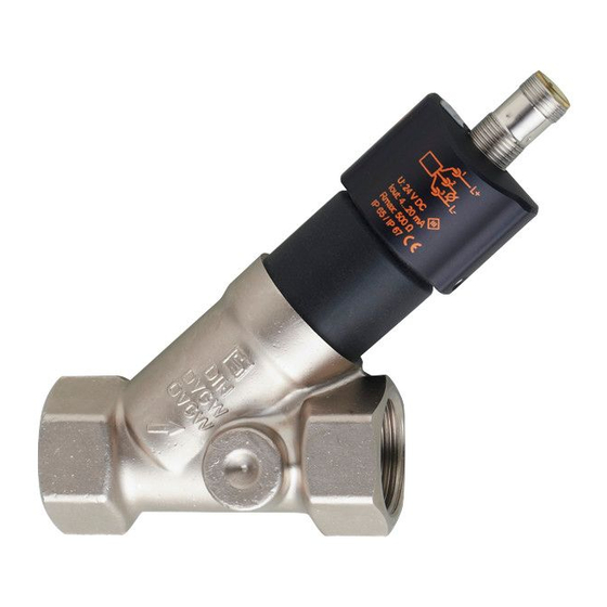
- Page 1 Operating instructions Mechatronic flow sensor SBx4xx...
-
Page 2: Table Of Contents
Contents 1 Preliminary note ....................2 2 Safety instructions ....................3 3 Functions and features ..................3 4 Function .......................4 5 Installation......................4 5.1 Installation in case of water containing dirt ............6 6 Electrical connection ....................6 7 Technical data and scale drawings ..............7 8 Troubleshooting ....................7 9 Maintenance, repair and disposal ................8 1 Preliminary note ►... -
Page 3: Safety Instructions
2 Safety instructions • The device described is a subcomponent for integration into a system. - The manufacturer is responsible for the safety of the system. - The system manufacturer undertakes to perform a risk assessment and to create a documentation in accordance with legal and normative requirements to be provided to the operator and user of the system. -
Page 4: Function
4 Function Q [l/min] 1: final value of the measuring range The analogue signal for water (20 °C) is linear from 4 mA (= no flow) to 20 mA (= final value of the measuring range, see Technical Data). For an output signal > 20 mA the volumetric flow is above the final value of the measuring range. - Page 5 ► Insert the unit into the pipe according to the direction of flow (arrow) and tighten. IN = inlet; OUT = outlet Calming sections on the sensor's inlet or outlet side are not necessary. ► Avoid major changes of cross section on the inlet side. ►...
-
Page 6: Installation In Case Of Water Containing Dirt
5.1 Installation in case of water containing dirt In water containing dirt, horizontal installation is recommended. ► Adhere to the inclination angle to the horizontal axis: ± 90° In clean water, installation in vertical pipes is also possible. 6 Electrical connection The unit must be connected by a qualified electrician. -
Page 7: Technical Data And Scale Drawings
7 Technical data and scale drawings Technical data and scale drawing at www.ifm.com. 8 Troubleshooting If there are dirt particles between the float and the housing the display value of the sensor does not return to zero in case of flow standstill. In case of dirt the display value can be up to 30 % of the final value of the measuring range. -
Page 8: Maintenance, Repair And Disposal
9 Maintenance, repair and disposal If used correctly, no maintenance and repair measures are necessary. Only the manufacturer is allowed to repair the unit. After use dispose of the unit in an environmentally friendly way in accordance with the applicable national regulations. In case of heavily polluted media: ►... - Page 9 More information at www.ifm.com...
Need help?
Do you have a question about the SB 4 Series and is the answer not in the manual?
Questions and answers