Sign In
Upload
Download
Table of Contents
Contents
Add to my manuals
Delete from my manuals
Share
URL of this page:
HTML Link:
Bookmark this page
Add
Manual will be automatically added to "My Manuals"
Print this page
×
Bookmark added
×
Added to my manuals
Manuals
Brands
IFM Electronic Manuals
Accessories
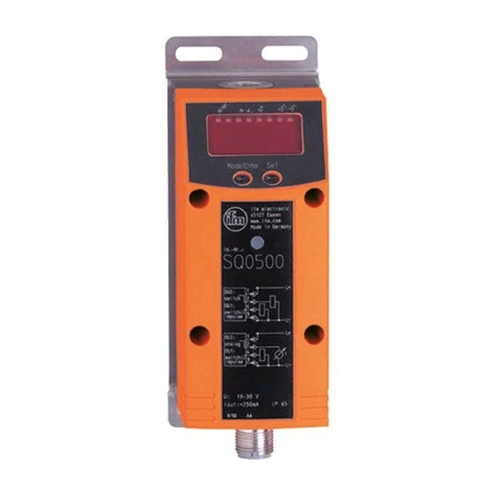
SQ0500
Operating instructions manual
IFM Electronic SQ0500 Operating Instructions Manual
Volumetric flow sensor
Hide thumbs
1
Table Of Contents
2
3
4
5
6
7
8
9
10
11
12
13
14
15
16
17
18
19
20
21
22
23
24
25
26
page
of
26
Go
/
26
Contents
Table of Contents
Bookmarks
Table of Contents
Table of Contents
Preliminary Note
1�1 Symbols Used
Safety Instructions
Functions and Features
Function
4�1 Processing of the Measured Signals
4�2 Volumetric Flow Monitoring
4�3 Consumed Quantity Meter
4�4 Consumed Quantity Monitoring with Pulse Output
4�5 Consumed Quantity Monitoring with Preset Counter
4�6 Temperature Monitoring
4�7 Volumetric Flow or Temperature Monitoring / Switching Function
4�8 Volumetric Flow or Temperature Monitoring / Analogue Function
4�9 Customer-Specific Calibration (CGA)
Installation
Electrical Connection
Operating and Display Elements
Menu
8�1 Menu Structure
8�2 Explanation of the Menu
Parameter Setting
9�1 General Parameter Setting
9�2 Settings for Volumetric Flow Monitoring
9�2�1 Settings for Limit Value Monitoring with OUT1
9�2�2 Settings for Limit Value Monitoring with OUT2
9�2�3 Setting the Analogue Value for Volumetric Flow
9�3 Settings for Consumed Quantity Monitoring
9�3�1 Settings for Quantity Monitoring Via Pulse Output
9�3�2 Settings for Quantity Monitoring Via the Preset Counter
9�3�3 Settings for Program-Controlled Counter Reset
9�3�4 Deactivation of the Counter Reset
9�4 Settings for Temperature Monitoring
9�4�1 Settings for Limit Value Monitoring with OUT2
9�4�2 Setting the Analogue Value for Temperature
9�5 User Settings (Optional)
9�5�1 Setting of the Standard Unit of Measurement for Volumetric Flow
9�5�2 Configuration of the Standard Display
9�5�3 Calibration of the Curve of Measured Values
9�5�4 Calibration Reset
9�5�5 Setting of Measured Value Damping
9�5�6 Setting the Error Behaviour of the Outputs
9�6 Service Functions
9�6�1 Reading of the Min/Max Values for Volumetric Flow
9�6�2 Reset of All Parameters to Factory Setting
9�7 Setting of the Preset Counter / Pulse Value (Imps)
Operation
10�1 Reading of the Set Parameters
10�2 Changing the Display Unit in the Run Mode
10�3 Fault Indication
10�4 General Operating Conditions
Scale Drawing
Technical Data
12�1 Setting Ranges
Factory Setting
Advertisement
Quick Links
1
Table of Contents
Download this manual
Operating instructions
Volumetric flow sensor
UK
SQ0500
Table of
Contents
Previous
Page
Next
Page
1
2
3
4
5
Advertisement
Table of Contents
Need help?
Do you have a question about the SQ0500 and is the answer not in the manual?
Ask a question
Questions and answers
Related Manuals for IFM Electronic SQ0500
Accessories IFM Electronic SM7000 Operating Instructions Manual
Magnetic-inductive flow sensor (31 pages)
Accessories IFM Electronic SU7000 Operating Instructions Manual
Efector 300 series ultrasonic flow rate sensor (31 pages)
Accessories IFM Electronic SU9000 Operating Instructions Manual
Efector 300 series ultrasonic flow rate sensor (31 pages)
Accessories IFM Electronic Efector 300 Operating Instructions Manual
Mechatronic flow sensor (8 pages)
Accessories IFM Electronic SA series Operating Instructions Manual
Selection of the operating mode via io-link interface (9 pages)
Accessories IFM Electronic SBT6 Series Operating Instructions
Mechatronic flow sensor (5 pages)
Accessories IFM Electronic SB 4 Series Operating Instructions Manual
Mechatronic flow sensor (9 pages)
Accessories IFM Electronic SA 00 Series Operating Instructions Manual
Flow sensor (40 pages)
Accessories IFM Electronic SM6000 Operating Instructions Manual
Magnetic-inductive flow sensor (31 pages)
Accessories IFM Electronic LR3000 Operating Instructions Manual
Electronic level sensor (30 pages)
Accessories IFM Electronic LR3000 Operating Instructions Manual
Electronic level sensor (39 pages)
Accessories IFM Electronic PN5 series Operating Instructions Manual
Electronic pressure sensor (33 pages)
Accessories IFM Electronic LK31xx Operating Instructions Manual
Electronic level sensor (36 pages)
Accessories IFM Electronic LK1022 Operating Instructions Manual
Electronic level sensor lk10 series lk70 series (35 pages)
Accessories IFM Electronic LK8122 Operating Instructions Manual
Electronic level sensor (39 pages)
Accessories IFM Electronic PN72 Series Operating Instructions Manual
Electronic pressure sensor (25 pages)
Summarization of Contents
Preliminary Note
Symbols and Abbreviations
Explains the meaning of symbols and abbreviations used throughout the manual.
Safety Instructions
Functions and Features Overview
Functionality Details
Signal Processing and Outputs
Details how the unit processes measured signals and generates output signals.
Volumetric Flow Monitoring
Describes the unit's capability to monitor volumetric flow and provide switching or analogue outputs.
Consumed Quantity Meter Function
Explains the internal meter that totals volumetric flow quantity for consumed quantity measurement.
Functionality Details
Quantity Monitoring via Pulse Output
Details how the unit provides a counting pulse based on reached quantity values.
Quantity Monitoring via Preset Counter
Describes two types of quantity monitoring using a preset counter: time-dependent and not time-dependent.
Temperature Monitoring Function
Explains temperature monitoring capabilities, including switching and analogue signal outputs.
Functionality Details
Switching Function for Flow/Temp Monitoring
Explains switching functions based on set limits, including hysteresis and window functions.
Analogue Function for Flow/Temp Monitoring
Details the analogue output configuration, including start and end points for signals.
Functionality Details
Customer-Specific Calibration (CGA)
Allows adjustment of the measured value curve gradient for custom calibration.
Installation Guide
Electrical Connection Procedure
Device Interface and Controls
Indicator LEDs Description
Details the function of each numbered LED indicator on the device.
Alphanumeric Display Details
Explains the 4-digit alphanumeric display and its indications.
Mode/Enter Button Function
Describes the function of the Mode/Enter button for parameter selection and acknowledgement.
Set Button Function
Explains the function of the Set button for parameter value adjustment and display unit changes.
Menu System Overview
Menu Structure Diagram
Presents a visual overview of the device's menu hierarchy and parameters.
Menu System Overview
Menu Item Explanations
Provides detailed explanations for each parameter and function within the device's menu.
Parameter Configuration
General Parameter Setting Procedure
Explains the basic three steps for setting any parameter in the unit.
Parameter Configuration
Menu Navigation, Locking, and Timeout
Covers switching between menu levels, locking/unlocking the unit, and timeout behaviour.
Parameter Configuration
Volumetric Flow Parameter Settings
Configures limit values and analogue outputs for volumetric flow monitoring.
Consumed Quantity Parameter Settings
Sets up quantity monitoring via pulse output or preset counter, and counter reset options.
Parameter Configuration
Temperature Parameter Settings
Configures limit values and analogue outputs for temperature monitoring.
Parameter Configuration
Optional User Settings
Optional settings for display units, calibration, and measured value damping.
Parameter Configuration
Output Error Behaviour Settings
Defines how outputs behave in case of a fault.
Service and Diagnostic Functions
Accesses diagnostic functions like reading min/max values and resetting parameters.
Parameter Configuration
Preset Counter / Pulse Value (ImPS) Setting
Configures the preset counter or pulse value for quantity monitoring.
Operation
Reading Configured Parameters
Explains how to view the currently configured parameters on the device.
Changing Display Unit in Run Mode
Describes how to change the displayed unit of measurement while in Run mode.
Fault Code Indications
Lists and explains the different fault codes and their meanings.
Operation
General Operating and Maintenance
Provides advice on maintaining the unit and ensuring optimal operating conditions.
Dimensional Scale Drawing
Technical Specifications
Parameter Setting Ranges
Details the minimum and maximum setting ranges for various parameters like flow, temperature, and ImPS.
Default Factory Settings
Table of Contents
Print
Rename the bookmark
Delete bookmark?
Delete from my manuals?
Login
Sign In
OR
Sign in with Facebook
Sign in with Google
Upload manual
Upload from disk
Upload from URL
Need help?
Do you have a question about the SQ0500 and is the answer not in the manual?
Questions and answers