Table of Contents
Advertisement
Advertisement
Table of Contents

Related Manuals for IFM Electronic SU7000


Summary of Contents for IFM Electronic SU7000
- Page 1 Operating instructions Ultrasonic flow rate sensor SU7000 SU8000 SU9000...
-
Page 2: Table Of Contents
Contents 1 Preliminary note ���������������������������������������������������������������������������������������������������4 1�1 Symbols used ������������������������������������������������������������������������������������������������4 1�1 Warning signs used ���������������������������������������������������������������������������������������4 2 Safety instructions �����������������������������������������������������������������������������������������������4 3 Functions and features ����������������������������������������������������������������������������������������5 4 Function ���������������������������������������������������������������������������������������������������������������6 4�1 Process measured signals ����������������������������������������������������������������������������6 4�2 Volumetric flow monitoring �����������������������������������������������������������������������������6 4�3 Consumed quantity monitoring (totaliser function) ����������������������������������������6 4�3�1 Consumed quantity monitoring with pulse output ���������������������������������7 4�3�2 Consumed quantity monitoring with preset counter �����������������������������7 4�4 Temperature monitoring ���������������������������������������������������������������������������������7... -
Page 3: Preliminary Note
12 Technical data ��������������������������������������������������������������������������������������������������31 13 Factory setting �������������������������������������������������������������������������������������������������32 1 Preliminary note 1.1 Symbols used ► Instructions > Reaction, result […] Designation of keys, buttons or indications → Cross-reference Important note Non-compliance can result in malfunction or interference� 1.1 Warning signs used CAUTION Warning of personal injury�... -
Page 4: Functions And Features
liability for consequences of misuse by the operator� Improper installation and use of the devices results in a loss of the warranty claims� • For medium temperatures above 50 °C some parts of the housing can heat up to over 65 °C� Moreover, during installation or in case of a fault (e�g� housing damage) media under high pressure or hot media can leak from the system�... -
Page 5: Function
4 Function 4.1 Process measured signals The unit displays the current process values� It generates 2 output signals according to the parameter setting� OUT1: 3 selection options Parameter setting - Switching signal for volumetric flow quantity limit value (→ 10.2.1) - or pulse signal for quantity meter (→... -
Page 6: 4�3�1 Consumed Quantity Monitoring With Pulse Output
The meter saves the totalled consumed quantity every 10 minutes� After a power failure this value is available as the current meter reading� If a time-controlled reset is set, the elapsed time of the set reset interval is also saved� So the possible data loss can be maximum 10 minutes� The meter can be reset as follows: →... -
Page 7: 4�5�1 Hysteresis Function
4.5.1 Hysteresis function Normally open: [OUx] = [Hno] Normally closed: [OUx] = [Hnc] First the set point (SPx) is set, then the reset point (rPx) with the requested difference� When SPx is adjusted, rPx is changed automatically; the differ- ence remains constant� Example of volumetric flow monitoring HY = hysteresis 4.5.2 Window function... -
Page 8: 4�6 Volumetric Flow Or Temperature Monitoring / Analogue Function
4.6 Volumetric flow or temperature monitoring / analogue function 4.6.1 Voltage output 0 ... 10 V (example volumetric flow monitoring) Factory setting Measuring range scaled U [V] U [V] MEW = final value of the measuring range ASP = analogue start point: determines at which measured value the output signal is 4 mA AEP = analogue end point: determines at which measured value the output signal is 20 mA�... -
Page 9: 4�6�2 Current Output 4
4.6.2 Current output 4 ... 20 mA (example volumetric flow monitoring) Factory setting Measuring range scaled I [mA] I [mA] MEW = final value of the measuring range ASP = analogue start point: determines at which measured value the output signal is 4 mA AEP = analogue end point: determines at which measured value the output signal is 20 mA�... - Page 10 After the start of the start-up delay there are 3 options: 1� The volumetric flow increases quickly and reaches the set point / good range within dST� > Outputs remain active� 2� The volumetric flow increases slowly and does not reach the set point /good range within dST�...
- Page 11 Example: dST for window function Condition Reaction 1 Volumetric flow quantity Q reaches 0�5 % dST starts, output becomes active of VMR 2 dST elapsed, Q reached good range output remains active 3 Q above SP (leaves good range) output is reset 4 Q again below SP output becomes active again 5 Q below rP (leaves good range)
-
Page 12: 4�8 Customer-Specific Calibration (Cga)
4.8 Customer-specific calibration (CGA) The customer-specific calibration allows changing the gradient of the curve of measured values (→ 10.5.4)� It influences the display and the outputs� 140 % MEW A = operating value for display and output signals 100 % MEW Q = flow MEW = final value of the measuring range 60 % MEW... -
Page 13: Installation
It applies in particular: No shut-off and control devices are allowed directly in front of the unit� a x D b x D S = disturbance SU7000, SU8000: a = 5 b = 2 D = pipe diameter SU9000: a = 8 b = 3 F = flow direction... -
Page 14: 5�2 Non Recommended Installation Position
5.2 Non recommended installation position ► Avoid the following installation positions: Directly in front of a falling pipe� In a falling pipe� At the highest point of the pipe Directly in front of the spout of the system� pipe� Flow rate direction horizontal, unit On the suction side of a pump�... -
Page 15: 5�3 Installation In Pipes
After installation air bubbles in the system can affect the measurement� Corrective measures: ► Rinse the system after installation for ventilation� - Rinsing quantity for SU7000 / SU8000: > 3 l/min - Rinsing quantity for SU9000: > 20 l/min� 6 Electrical connection The unit must be connected by a qualified electrician�... - Page 16 BK: black BN: brown OUT2 BU: blue OUT1 WH: white Colours to DIN EN 60947-5-2 Sample circuits: 2 x positive switching 2 x negative switching 1 BN 1 BN 2 WH 2 WH 4 BK 4 BK 3 BU 3 BU 1 x positive switching / 1 x analogue 1 x negative switching / 1 x analogue 1 BN...
-
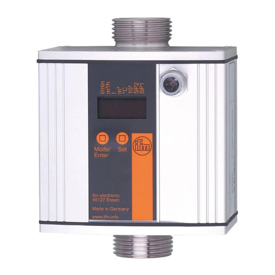
Page 17: Operating And Display Elements
7 Operating and display elements Mode/ Enter 1 to 8: Indicator LEDs • LEDs 1-6 = unit of the currently represented numerical value → 11.1 Reading the process value • LED 7 = switching status of output OUT2 / of input InD •... -
Page 19: Menu
8 Menu 8.1 Menu structure l/min l* m °C Mode/Enter l or m = current meter count in l, m or 1000m l*or m * = stored meter count in l, m or 1000 m... -
Page 20: 8�2 Explanation Of The Menu
8.2 Explanation of the menu SP1 / rP1 Upper / lower limit value for volumetric flow ImPS Pulse value Pulse repetition active (= pulse output function) or not active ImPR (= preset counter function) Output function for OUT1 (volumetric flow or consumed quantity): - Switching signal for the limit values: hysteresis function or window func- tion, either normally open or normally closed - Pulse or switching signal for quantity meter... -
Page 21: Set
9 Set-up After power on and expiry of the power-on delay time of approx� 10 s the unit is in the Run mode (= normal operating mode)� It carries out its measurement and eval- uation functions and generates output signals according to the set parameters� •... -
Page 22: 10�1 Parameter Setting In General
10.1 Parameter setting in general 3 steps must be taken for each parameter setting: Select parameter ► Press [Mode/Enter] until the re- quested parameter is displayed. Mode /Enter Set parameter value ► Press and hold [Set]� > Current setting value of the param- eter flashes for 5 s�... - Page 23 10.1.2 Locking / unlocking The unit can be locked electronically to prevent unintentional settings� Locking: ► Make sure that the unit is in the normal operating mode� ► Press [Mode/Enter] + [Set] for 10 s� Mode /Enter > [Loc] is displayed� During operation: [LOC] is briefly displayed if you try to change parameter values�...
- Page 24 10.2.2 Configure limit value monitoring with OUT2 ► Select [SEL2] and set [FLOW]� ► Select [OU2] and set the switching function: - [Hno] = hysteresis function/normally open, - [Hnc] = hysteresis function/normally closed, - [Fno] = window function/normally open, - [Fnc] = window function/normally closed� ►...
- Page 25 10.3.3 Setting the pulse value ► Select [ImPS]� ► Press and hold [Set]� > The current numerical value flashes for 5 s, then one of the 4 digits becomes active and can be changed as below: 1� Briefly press [Set] >...
- Page 26 10.3.5 Time-controlled counter-reset ► Select [rTo]� ► Press [Set] until the requested value is displayed (intervals from 1 hour to 8 weeks)� ► Briefly press [Mode/Enter]� > The counter is reset automatically with the value now set� 10.3.6 Deactivate meter reset ►...
- Page 27 10.5 User settings (optional) 10.5.1 Set standard unit of measurement for volumetric flow ► Select [Uni] and set the unit of measurement: [Lmin] or [m3h]� The setting only has an effect on the volumetric flow value� The counter values (consumed quantity) are automatically displayed in the unit of measurement providing the highest accuracy�...
- Page 28 10.5.7 Set measured value damping ► Select [dAP] and set the damping constant in seconds (τ value 63 %). 10.5.8 Set output status in fault condition ► Select [FOU1] and set the value: - [On] = output 1 switches ON in case of an error� - [OFF] = output 1 switches OFF in case of a fault�...
- Page 29 11 Operation 11.1 Reading the process value The LEDs 1-6 signal which process value is currently displayed� The process value to be displayed as standard (temperature, flow velocity or me- ter reading of the totaliser) can be preset (→ 10.5.2 Configuration of the standard display)�...
-
Page 30: Technical Data
11.3 Read set parameters ► Briefly press [Mode/Enter] to scroll the parameters� ► Briefly press [Set] when the requested parameter is displayed� > The unit displays the corresponding parameter value� After about 15 s it again displays the parameter, then it returns to the Run mode� 11.4 Fault indications [SC1] Short circuit in OUT1�... - Page 31 13 Factory setting User Factory setting setting SU7000 SU8000 SU9000 10�0 20�0 40�0 5�0 10�0 20�0 ImPS 0�1 0�1 0�1 ImPR 40�0 80�0 160�0 SP2 (FLOW) 30�0 60�0 120�0 rP2 (FLOW) SP2 (TEMP) 62�0 62�0 62�0 44�0 44�0 44�0 rP2 (TEMP) ASP (FLOW) 0�0...
Need help?
Do you have a question about the SU7000 and is the answer not in the manual?
Questions and answers