Table of Contents
Advertisement
Quick Links
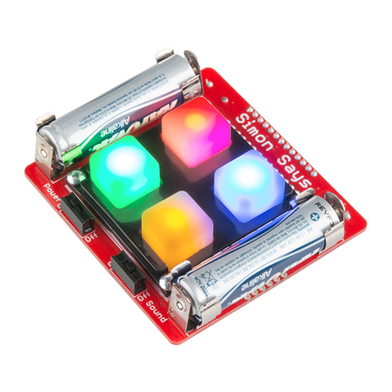
Simon Says Assembly Guide
Introduction
If you've found yourself here, chances are you've purchased one of our many Simon Says Through-Hole soldering
kits. This tutorial will help you become familiar with the tools you'll need to build the Simon Says, show you how to
build it, and show you how you can take this simple, yet fun, game further with a little bit of programming know-
how. The different kits encompassed in this tutorial include:
SparkFun Simon Says - Through-Hole Soldering Kit
KIT-10547
O
O
U
C
C
A
R
U
T
N
Y
R
T
E
S
I
G
E
R
Advertisement
Table of Contents

Related Manuals for sparkfun Simon Says


Summary of Contents for sparkfun Simon Says
- Page 1 If you've found yourself here, chances are you've purchased one of our many Simon Says Through-Hole soldering kits. This tutorial will help you become familiar with the tools you'll need to build the Simon Says, show you how to build it, and show you how you can take this simple, yet fun, game further with a little bit of programming know- how.
-
Page 2: Suggested Reading
To make things simple, we'll cover everything from the tools to building the Simon Says all in this tutorial. If you feel comfortable enough with soldering and are just looking for some detailed instructions on how to put your kit together, you may want to skip ahead. -
Page 3: Required Tools
If you've purchased the Simon Says - Through-Hole Kit or Retail Kit, the following is a recommended list of materials you'll need to complete the build. If you have a Learn to Solder: Simon Says, your kit should include all... - Page 4 SparkFun Safety Glasses TOL-09477 SWG-11046 Diagonal Cutters TOL-08794 Inside the Simon Says Through-Hole kit, you'll find all the parts for the Simon Says. This includes: ATmega328 - pre-programmed with Simon firmware Buzzer 0.1μF Cap (x2) 10K Resistor...
- Page 5 Missing any parts? Sometimes one of those tiny little components can get misplaced. If you're missing any parts contact our customer service team, and we'll get you the missing parts in a jiffy. Quickstart - Soldering Basics and Advice There are some basic tips that will help you achieve the best solder connection possible, help keep your soldering iron in good condition and also keep you safe.
- Page 6 The next bit of advice is always keep your iron in its stand while your not using it. Setting down your iron on your workspace can be a major hazard. Not only can you burn the other items on your workbench, but you can also set your arm down on it and get a gnarly burn (I speak from experience).
- Page 7 Now that we've covered proper soldering iron handling and care, let's go over how to properly use it. There is a correct way to solder, and it takes lots of practice to master. Getting it right early on will make your soldering experience a lot more fun.
- Page 8 We'll go over over in detail how to solder on the first part. Then we'll show you which parts go where and let you have at it. The booklet that comes with the Simon Says has been carefully crafted and goes over the assembly in lots of detail.
- Page 9 Locate the 10kΩ resistor. If you look closely, it has a specific pattern of stripes on it: BROWN, BLACK, ORANGE, GOLD. Note: The patten can be in the opposite order; this is still the correct resistor. To further understand resistor markings, please check out the following tutorial: Decoding Resistor Markings.
- Page 10 Push the resistor in so it is nearly flush with the board. Note: This component is not polarized and so it does not matter which leg goes into each hole. Some components in this kit are polarized and we will take extra care when we get to them to ensure they are ...
- Page 11 Feed solder into the joint. First, pull away the solder. Second, pull away the iron. Your solder joints should look like this - a tiny volcano. Clip off any excess legs.
- Page 12 Note: The resistor tells the microcontroller not to reset once the power is turned on, so your game can continue uninterrupted. Try to be gentle with the board, but a few scratches are not a big deal. Capacitors Locate the two 0.1uF decoupling capacitors. These look a little different than resistors. They have two leads than come down off the bottom of the component, and they have the markings “104”...
- Page 13 Locate the microcontroller. This component is polarized, which means we need to take extra care to place it in the board properly. Notice the notch on the image below. Looking at the bottom of the board, insert the microcontroller .
- Page 14 Locate the position on the PCB. Note the “+” on the buzzer . The “+” on the buzzer should align with the white “+” on the board. Flip the board over and solder the buzzer's pins. Note: The buzzer makes the noise for the game - pretty simple! LEDs Polarized Pay special attention to the component’s markings indicating how to place it on the PCB.
- Page 15 The LEDs are polarized. This means there are “-” and “+” legs. Each LED has a short leg and a long leg. The short leg goes into the hole labeled “-”. Locate their positions on the PCB. Insert the four LEDs into the top of the board. Also, make sure it sits flush with the PCB. Then solder them into place.
- Page 16 Polarized Pay special attention to the component’s markings indicating how to place it on the PCB. Component Polarized components can only be connected to a circuit in one direction. Locate the four battery clips. Locate their positions on the PCB. Insert the battery clips .
-
Page 17: Final Assembly
Locate their positions on the PCB. Looking at the top of the board, insert the switches. Keep the iron tip away from the black plastic! Plastic melts easily. Flip the board over. Then begin to solder. Note: The slide switches turn on and off the power and sound. Final Assembly Polarized Pay special attention to the component’s markings indicating how to place it on the PCB. - Page 18 They also hold the pad and bezel onto the board. With that, you should have a fully functional Simon Says that you built yourself! Turn it on by flipping the “Power” and “Sound” switch to the “On” position to see if it works.
- Page 19 Just for fun, try this out. Don’t worry, it won’t change your Simon permanently. Turn the power switch to the “Off” position. Press any one button. While holding the button down, turn the Simon Says back on to test out one of the special modes that we have included!
-
Page 20: Troubleshooting
Troubleshooting If your Simon doesn't work right off the bat, don't fret. There are many ways that your board could have an error on it. Look over these troubleshooting tips to help diagnose the problem. This section also goes over how to use the solder wick that came with your kit. - Page 21 Solder Jumpers Did you accidentally solder a jumper between two legs where it should not be included? Don't fret. Here is a simple process using solder wick to remove the excess solder. Locate a solder wick. Place solder wick on top of solder. Place iron on top of solder wick.
- Page 22 Building the Simon PTH Kit Note: Please note that the video showcases a different version of the Simon Says, but it still highlights all the main components and shows you the proper way to assemble them.
-
Page 23: Arduino Ide
DEV-09873 PRT-00116 SparkFun USB Mini-B Cable - 6 Foot CAB-11301 To learn how to use the Simon Says with the Arduino IDE, we have a few tutorials. To get started, it is recommended to start with this tutorial:... - Page 24 Simon Says Experiments OCTOBER 21, 2010 So you've built up a Simon Says kit? What next? This tutorial will get you up and running with Arduino software, guide you through a few example sketches, and send you on your way to create your own. Careful, this stuff is highly addictive. :)
- Page 25 Simon Says Experiments So you've built up a Simon Says kit? What next? This tutorial will get you up and running with Arduino software, guide you through a few example sketches, and send you on your way to create your own. Careful, this stuff is highly addictive.
Need help?
Do you have a question about the Simon Says and is the answer not in the manual?
Questions and answers