Table of Contents
Advertisement
Quick Links
FreeSoC2 Hookup Guide V14
Introduction
Note: This guide is for the latest version of the FreeSoC2, V14. If You have an older version (the version
number can be found on the back of the PCB), please refer to this tutorial.
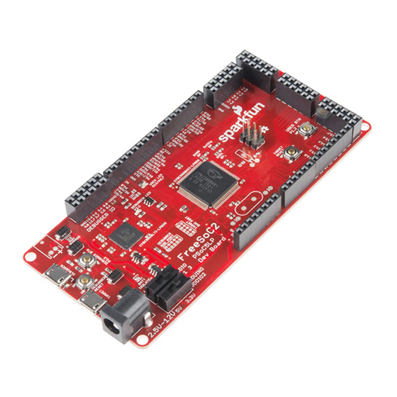
The FreeSoc2 is SparkFun's PSoC5LP development board features a full onboard debugger, support for 5V and
3.3V IO voltages, and a CY8C5888AXI-LP096 processor with 256kB of flash, 64kB of SRAM and 2kB of
EEPROM. The onboard oscillator can drive the processor at up to 80MHz, and the Cortex-M3 core provides
superior performance.
FreeSoC2 Development Board - PSoC5LP
DEV-13714
The real power of the PSoC5LP isn't in the processor, however. Wrapped around the processor is a rich analog
and digital programmable fabric, which can be configured to provide many functions that would otherwise need to
be realized in code (lowering system performance) or external circuitry (adding cost and board size). In addition,
Advertisement
Table of Contents

Related Manuals for sparkfun FreeSoC2


Summary of Contents for sparkfun FreeSoC2
- Page 1 FreeSoC2 Hookup Guide V14 Introduction Note: This guide is for the latest version of the FreeSoC2, V14. If You have an older version (the version number can be found on the back of the PCB), please refer to this tutorial.
-
Page 2: Required Materials
We’re going to keep it simple; the FreeSoC2 has an onboard LED and user-accessible pushbutton. We’ll use those for our lessons. That means you’ll only need the FreeSoC2 board and a micro-B USB cable. You may, however, find it useful to have a second USB cable, as that will allow you to connect to both the debugger and the target at the same time. - Page 3 1. 5.5mm x 2.1mm center positive barrel jack – This fits all of SparkFun’s standard “wall wart” type power supplies. While the regulators on the FreeSoC2 can handle input voltages up to 12V, it’s best to keep the input voltage as close to 5V as possible.
-
Page 4: Using The Arduino Ide
I C bus. 14. Battery Supply Diode Bypass – If you populate the 2.5mm JST connector and run the FreeSoC2 off of a LiPo battery, you may find the ~0.5V drop across the diode which ORs the battery supply into the main supply rail. - Page 5 FreeSoC2 within the IDE! Currently, the only way to add the FreeSoC2 support to the Arduino IDE is to download the files directly and manually install them. Instructions on how to do so are below. The first step is to use the Board Manager to add support for the ARM processor core.
- Page 6 Programming the FreeSoC2 Board With an Arduino Bootloader If you’ve purchased an early version of the FreeSoC2 (V11 or earlier; look on the back of the board, under the power connector for the version number), or if you’ve previously used the PSoC Creator software to develop on your FreeSoC2 board, you’ll find that it will not respond to the bootloading commands of the Arduino IDE.
- Page 7 Do not connect to the “Target” port at this time. 2. The drivers for the KitBridge programmer/debugger (onboard the FreeSoC2) have already been installed as part of the Programmer installation. If Windows fails to detect them automatically, they can be found in the Programmer installation directory.
- Page 8 The core support for the PSoC is made to closely resemble the Arduino Uno R3, and by and large, code which runs on the Uno R3 will work on the FreeSoC2 with little or no change. Here are some of the differences to be aware of: 1.
- Page 9 Developed/Tested with: FreeSoC2 Arduino.cc IDE 1.6.4 This code is beerware; if you see me (or any other SparkFun employee) at the local, and you've found our code helpful, please buy us a round! Distributed as-is; no warranty is given. ******************************************************************************/ // Note the use of long here instead of int! This is important.
-
Page 10: Connecting The Board
digitalWrite(LEDPin, LOW); delay(250); Getting Started with PSoC Creator If you want to move beyond the basics, you’ll need to install Cypress’s PSoC Creator IDE. It’s free, with no code size limitations, although Cypress does ask that you register before downloading. It is, sadly, Windows only. - Page 11 That will open this window. I’ve clicked the ‘+’ next to “Advanced” to show more choices. The first thing to do is to select “PSoC 5LP Design” from the “Default Templates” list. This will set up some things for you, including setting compiler options and paths. The “Name”...
-
Page 12: Adding Hardware
“Sheet template” is the size and format of the schematic capture sheet you’ll use to define the hardware components of your design. I’ve selected 11"x17" ledger size, and that’s a good place to start until you’ve gotten accustomed to breaking projects up into smaller chunks and making components in libraries. Finally, you have the option to select whether your application is a bootloader, is bootloadable, or is a multi-app bootloader (to provide fail-safe operation). - Page 13 I’ve pulled a couple of components over from the component catalog, here: from “Ports and Pins”, a “Digital Input Pin” and a “Digital Output Pin”, and from the off-chip portion, a switch, resistor, and LED. Again, those off-chip parts are purely aesthetic and have no more effect on the generated output than if you were to draw a picture of a butterfly on the schematic.
- Page 14 On the right side, there’s a list of pin objects, port pins, and physical pin numbers. If you don’t assign a pin to a physical port, the IDE will do it for you. On the FreeSoC2, the user button is attached to port 1, pin 2, and the user LED to port 6, pin 7, so let’s make those assignments now.
- Page 15 Here’s our main.c file. This is automatically generated, and you can safely alter it without worrying about the IDE breaking it. Put this code into the loop section: for(;;) if (Button_Pin_Read() == 0) LED_Pin_Write(1); else LED_Pin_Write(0); It’s pretty simple: turn the LED on when the button is pressed and off when it’s released. Now, you can upload the code to the processor.
- Page 16 Forums - Cypress also has a thriving forum community. Reddit - There’s a fairly active subreddit for the PSoC, as well. Video tutorials - Official PSoC Creator training videos. These are information dense and super helpful. For more FreeSoC2 fun, check out these other SparkFun tutorials…...
- Page 17 Making Music with the FreeSoC2 AUGUST 14, 2015 Create a synth keyboard with the FreeSoC2 from SparkFun.
Need help?
Do you have a question about the FreeSoC2 and is the answer not in the manual?
Questions and answers