Advertisement
Quick Links
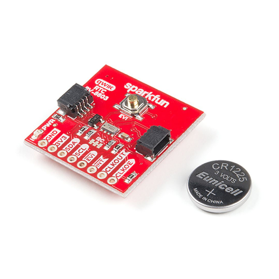
Real Time Clock Module - RV-8803 (Qwiic) Hookup Guide
Introduction
The Real Time Clock Module - RV-8803 (Qwiic) is a Qwiic-enabled breakout board for the RV-8803 RTC module. The RV-8803 boasts some impressive
features including a temperature compensated crystal, extremely precise time-keeping, low power consumption, time stamp event input along with a
user-programmable timing offset value. It even has a programmable Clock Output to control precise timing for peripheral devices. The RV-8803 also has
2
an improved I C interface compared to the RV-1805 RTC that removes the need to sequence commands/writes to the device. This is particularly helpful if
you are not using our Arduino Library to control the RTC.
SparkFun Real Time Clock Module - RV-8803 (Qwiic)
BOB-16281
Advertisement

Subscribe to Our Youtube Channel
Related Manuals for sparkfun RV-8803


Summary of Contents for sparkfun RV-8803
- Page 1 Introduction The Real Time Clock Module - RV-8803 (Qwiic) is a Qwiic-enabled breakout board for the RV-8803 RTC module. The RV-8803 boasts some impressive features including a temperature compensated crystal, extremely precise time-keeping, low power consumption, time stamp event input along with a user-programmable timing offset value.
- Page 2 Product Showcase: SparkFun Qwiic Real Time Clock Module In this hookup guide we will go over the unique features of the RV-8803 along with some Arduino examples demonstrating how to use those features. By the end of this tutorial you will have your Real Time Clock Module - RV-8803 (Qwiic) configured and tick-tocking away (well, ticking, maybe not tocking)
- Page 3 SparkFun RedBoard Artemis DEV-15123 DEV-15444 If your chosen microcontroller is not already Qwiic-enabled, you can add that functionality with one or more of the following items: SparkFun Qwiic Cable Kit SparkFun Qwiic Shield for Arduino KIT-15081 DEV-14352...
- Page 4 SparkFun Qwiic Adapter SparkFun Qwiic Shield for Arduino Nano DEV-14495 DEV-16130 You will also want at least one Qwiic cable to connect your RTC to your microcontroller. Qwiic Cable - 100mm Qwiic Cable - 200mm PRT-14427 PRT-14428...
- Page 5 ADDITIONAL TOOLS FOR SOLDERING TO THE REAL TIME CLOCK MODULE RV-8803 BREAKOUT Finally, if you want to fine tune the RV-8803's oscillator for extremely precise time keeping you will need to use an oscilloscope or logic analyzer to calibrate it. Click the button below to see some options for oscilloscopes and logic analyzers if you need one.
-
Page 6: Hardware Overview
The heart of this breakout is the RV-8803 Real Time Clock module from Micro Crystal. In this section we'll cover most of the features and characteristics of the RV-8803 and this breakout but if you are looking for a more thorough synopsis of the RV-8803, take a look through the Application Manual . The table below lists some of the operating characteristics of the RV-8803. - Page 7 Qwiic and I C Interface The easiest way to use the Real Time Clock Module - RV-8803 (Qwiic) is with the Qwiic connect system. Just connect the board using a Qwiic Cable to your microcontroller to start talking to it. Alternatively, you can solder to the I C pins broken out on the board. The 7-bit I C unshifted address is 0x32 (0110010b).
- Page 8 Pin Descriptions While the Qwiic interface is the easiest and fastest way to start using your RTC, there are several other pins for extra functionality broken out. You will need to either solder to these pins to make use of them or you can create a temporary connection using something like these IC Hooks. The table below outlines all of the pins broken out on the RTC and summarizes their functionality.
- Page 9 Jumpers There are two jumpers on the SparkFun Real Time Clock Module - RV-8803 (Qwiic) labeled "I C" and "LED". The I C jumper is closed by default and can be opened by severing the trace between the three pads to disconnect the two 4.7k Ohm resistors from the SDA and SCL lines. Open this jumper for if you have many I C devices on the same bus or to reduce current draw for low-power projects.
-
Page 10: Board Dimensions
Board Dimensions The SparkFun Real Time Clock Module - RV-8803 (Qwiic) is built to the standard 1 x 1" size for Qwiic Breakouts. One thing you may notice is this board's lack of mounting holes. In order to fit the 1 x 1" standard for Qwiic Breakouts, there was no space for mounting holes as the battery holder takes the space normally reserved for those mounting holes. - Page 11 RTC at the same logic level. In order to use the full functionality of the RV-8803, you will want to solder to the EVI, INT, CLKOUT and CLKOE pins broken out on this board. If you are...
- Page 12 The easiest way to install the library is to search for SparkFun RV-8803 in the Arduino Library Manager tool. You can also manually install the RV-8803 Library from the GitHub Repository or you can download it by clicking the button below.
- Page 13 Alarm & Interrupt Functionality Since the RV-8803 has three types of alarms/interrupts, this list is quite extensive so we've split it up into the individual alarm and interrupt functionalities. External Event Interrupt - Enables or disables the the External Event Interrupt (EVI) button and pin.
- Page 14 - Returns whether or not the EVI Event Capture function is enabled or disabled. bool getEVIEventCapture(); Countdown Interrupt - Enables or disables the Periodic Countdown Timer interrupt function. bool setCountdownTimerEnable(bool timerState); - Sets the time for the Periodic Countdown Timer. Built in values are bool setCountdownTimerFrequency(uint8_t countdownTimerFrequency);...
- Page 15 This example demonstrates how to set the time on the RV-8803 RTC to either the compiler time or a custom time. This is necessary to set the RTC's internal clock to keep time so long as the RTC has power. First, the code initializes the RV-8803 on the I C bus and verifies the microcontroller can talk to it.
- Page 16 Example 2 - Print Time This example shows how to request the time from the RTC after it has been set. The code starts by initializing the RV-8803 on the I C bus then attempts to to move the values from the RV-8803's time registers to the microcontroller's array using the function.
- Page 17 Enabling this bit tells the RV-8803 to reset the hundredths register when it sees a LOW event on the EVI pin. This event can either be triggered by pressing the button or pulling the EVI pin LOW. The code will print the RV-8803 is ready for a button press or other event on the EVI pin. When that pin is triggered it prints out the the hundredths value pulled from the RV-8803's time register over serial.
- Page 18 CLICK HERE TO OPEN THE COUNTDOWN TIMER SETTINGS TABLE After initializing the RV-8803, the example configures a ~3.5 second interrupt. To do this, we first choose 60 Hz as our timer frequency since we want our timer longer than 1 second but still want a small enough time range (or resolution) to easily set the interrupt to fire at 3.5 secs and not 3 or 4 seconds.
- Page 19 Example 4C - Periodic Interrupt The last interrupt example demonstrates how to generate a periodic pulse from the RV-8803. This is very similar to the previous example but instead of setting a custom time between interrupts, we configure the RV-8803 to pulse the interrupt pin every second or every minute using the function.
- Page 20 Example 6 - Fine Tuning In order to follow this example you will need an oscilloscope or logic analyzer. If you have never used either of these tools, take a look at these tutorials to get started: How to Use an Oscilloscope FEBRUARY 25, 2014 How to work the dials and buttons on an oscilloscope, and a glossary of the o- scope lexicon.
-
Page 21: Troubleshooting
24MHz USB logic analyzer. This last example demonstrates how to calibrate the RV-8803's oscillator using the Clock Output pin. Again, we first initialize the RV-8803 on the I C bus. Next, we zero out any calibration settings that may be present and set the clock output to a 1 Hz square wave: rtc.disableAllInterrupts();... - Page 22 If you don't find what you need there, the SparkFun Forums are a great place to find and ask for help. If this is your first visit, you'll need to create a Forum Account to search product forums and post questions.
- Page 23 A quick introduction to the DS1307 RTC module and a hookup guide for and Pro R3 breakout boards. Level up your Arduino-skills with the the SparkFun Breakout. powerful ARM Cortex M0+ processor. Or check out some of these blog posts for project ideas:...
- Page 24 DIY Sunrise Alarm Nixie LED Clock MARCH 26, 2018 MAY 8, 2018...
Need help?
Do you have a question about the RV-8803 and is the answer not in the manual?
Questions and answers