Table of Contents
Advertisement
Quick Links
Page 1 of 27
P
M
A
Pro Micro & Fio v3 Hookup Guide
CONTR IBUTORS:
J IM B 0
Introduction
Welcome to the new frontier of Arduino-compatible boards, made possible
by the ATmega32U4. No longer does your Arduino need to be harnessed
by an FTDI Cable, or an ATmega8U2, or any chip who's sole purpose is
acting as an intermediary between your Arduino and your computer.
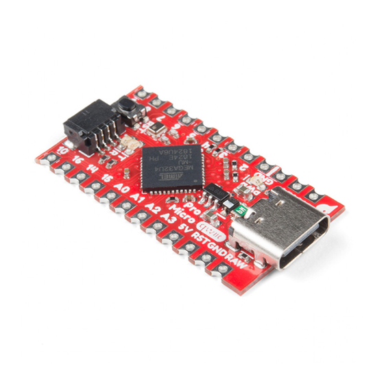
The SparkFun Pro Micro is a really cool, little development board. It's an
Arduino-compatible microcontroller, micro-sized, and it accomplishes with
one single chip what old Arduino Unos, Duemilanoves, and Diecimeillas
could never dream of: true USB functionality.
This tutorial also covers the Fio v3, which works a lot like the Pro Micro but
adds features like easy XBee interfacing and LiPo charging.
Advertisement
Table of Contents

Subscribe to Our Youtube Channel
Related Manuals for sparkfun Pro Micro


Summary of Contents for sparkfun Pro Micro
- Page 1 Arduino Unos, Duemilanoves, and Diecimeillas could never dream of: true USB functionality. This tutorial also covers the Fio v3, which works a lot like the Pro Micro but adds features like easy XBee interfacing and LiPo charging.
-
Page 2: Suggested Reading
This tutorial aims to introduce you to both the hardware and firmware sides of the Pro Micro (and Fio v3). We’ll also dedicate a few pages to helping install the boards on Windows and Mac. Here’s a summary of what will be covered: •... -
Page 3: Power Pins
‘RAW’ pin (or USB), this pin can be used as an output to supply other devices. • RST can be used to restart the Pro Micro. This pin is pulled high by a 10k&Ohm; resistor on the board, and is active-low, so it must be connected to ground to initiate a reset. -
Page 4: Onboard Leds
Page 4 of 27 I/O Pins The Pro Micro’s I/O pins – 18 in all – are multi-talented. Every pin can be used as a digital input or output, for blinking LEDs or reading button presses. These pins are referenced in the Arduino IDE via an integer value between 0 and 21. - Page 5 As the Pro Micro’s main feature is its innate USB functionality, the most common way to power it is via USB. In this setup, a 5V Pro Micro will be powered directly from the USB bus and a 3.3V Pro Micro will regulate the 5V supply coming in from USB down.
- Page 6 How, exactly, you power your project is up to you and the demands of your project. If you’re making something battery powered, you may want to opt for the 3.3V Pro Micro, which could be powered by a LiPo battery or a couple alkalines.
- Page 7 Two LEDs towards the bottom – labeled RX and TX – help indicate when data is transferring to and from the Fio through USB. A blue LED represents USB data coming into (‘RX’) the the Pro Micro, and a yellow LED indicates USB data going out (‘TX’).
- Page 8 Page 8 of 27 Finally, there’s a yellow LED labeled ‘CHG’ which indicates if an attached lithium polymer battery is charging. If a battery is not connected to the Fio, the LED will be in an undefined state, and most likely be illuminated. How to Power the Fio v3 The suggested power supply for the Fio v3 is any single-cell lithium polymer (LiPo) battery.
-
Page 9: Installing Windows
Installing: Windows Getting the Pro Micro or Fio v3 set up on your computer and in your Arduino environment can be difficult. Follow along on this page for a step- by-step guide through the driver installation and Arduino-enabling process. -
Page 10: Step 3: Open The Device Manager
Page 10 of 27 Never fear! Windows just doesn’t know where to find our driver. Note: Some users have experienced issues when plugging the Pro Micro into a USB 3.0 port. If you experience issues on USB 3.0 ports, try switching to use a USB 2.0 port. - Page 11 ‘Windows has successfully updated your driver software’ window. And the ‘Device Manager’ should have a new entry for the ‘SparkFun Pro Micro (COM ##)’ (or ‘SparkFun Fio V3 (COM##)’ if you have one of those) under the ‘Ports’ tree.
- Page 12 Page 12 of 27 Take note of which COM port your Pro Micro was assigned. We’ll need it soon. Installing the Arduino Addon We’re still not completely ready for Arduino, but this is the final stretch. Before you can use the ProMicro in the Arduino IDE, you need to enable it and activate some super-secret Arduino files.
-
Page 13: Board Installation
If you’re using Mac or Linux, follow the steps below to get your Pro Micro (or Fio v3) ready to go on your computer. We’re not going to name names here, but installing the Pro Micro on Mac OS X and Linux is a lot easier than on other OS’s…... - Page 14 Installing the Arduino Addon In order to use the Pro Micro or Fio v3 in your Arduino IDE, you need to add a few board definition files to it. That’s what we’ll do in this section. Begin by downloading the Pro Micro addon files.
- Page 15 If the boards are visible, select the option that matches your board. If you have a Pro Micro, make sure you select the correct operating speed and voltage! Then head over to the next page where we’ll upload our first...
- Page 16 Page 16 of 27 /* Pro Micro Test Code by: Nathan Seidle modified by: Jim Lindblom SparkFun Electronics date: September 16, 2013 license: Public Domain please use this code however yo u'd like. It's provided as a learning tool. This code is provided to show how to control the SparkFun ProMicro's TX and RX LEDs within a sketch. It also serves to explain the difference between Serial.print() and Serial1.print(). int RXLED = 17; // The RX LED has a defined Arduino pin // The TX LED was not so lucky, we'll need to use predefined // macros (TXLED1, TXLED0) to control that. // (We could use the same macros for the RX LED too RXLED1, // and RXLED0.) void setup() { pinMode(RXLED, OUTPUT); // Set RX LED as an output // TX LED is set as an output behind the scenes Serial.begin(9600); //This pipes to the serial monitor Serial1.begin(9600); //This is the UART, pipes to sensors att ached to board } void loop() { Serial.println("Hello world"); // Print "Hello World" to th e Serial Monitor Serial1.println("Hello!"); // Print "Hello!" over hardware U digitalWrite(RXLED, LOW); // set the LED on TXLED0; //TX LED is not tied to a normally controlled pin delay(1000); // wait for a second...
- Page 17 Since the bootloader and sketch run individually. Only one of these serial ports is visible at any one time. When you click ‘Upload’ in the Arduino IDE, the Pro Micro resets itself and starts its bootloader program. (The bootloader is a low-level program on the Pro Micro which enables self-programming via serial.) To our operating...
- Page 18 Example 2: HID Mouse and Keyboard By far, the Pro Micro’s most revolutionary feature (as far as Arduinos go) is its true USB functionality. The Pro Micro can be programmed to emulate any USB device you could imagine. You can even program it to act just like a mouse, keyboard, or other HID-class USB device.
- Page 19 } } In this sketch, connecting pin 9 to ground will make the Pro Micro spit out a ‘z’ character. If you have a simple, momentary button handy, tie one end to pin 9 and the other to ground. Otherwise, just use a wire to short 9 to GND.
- Page 20 Page 20 of 27 • tells the computer to move the mouse a Mouse.move(x, y, wheel) certain number of pixels along either the x, y and/or wheel axis. Each variable can be any value between -128 and +127, with negative numbers moving the cursor down/left, positive numbers move the right/up.
- Page 21 Page 21 of 27 /* HID Joystick Mouse Example by: Jim Lindblom date: 1/12/2012 license: MIT License Feel free to use this code for any p urpose. No restrictions. Just keep this license if you go on to us e this code in your future endeavors! Reuse and share. This is very simplistic code that allows you to turn the SparkFun Thumb Joystick (http://www.sparkfun.com/products/9 032) into an HID Mouse. The select button on the joystick is se t up as the mouse left click. */ int horzPin = A0; // Analog output of horizontal joystick pin int vertPin = A1; // Analog output of vertical joystick pin int selPin = 9; // select button pin of joystick int vertZero, horzZero; // Stores the initial value of each a xis, usually around 512 int vertValue, horzValue; // Stores current analog output of each axis const int sensitivity = 200; // Higher sensitivity value = sl ower mouse, should be <= about 500 int mouseClickFlag = 0;...
-
Page 22: Troubleshooting And Faq
On this page you’ll find troubleshooting tips and FAQs. Here’s a directory of the subjects covered: • Troubleshooting ◦ Serial Port Not Showing Up in “Tools > Board” menu ◦ How to Reset to Bootloader ◦ How to Revive a “Bricked” Pro Micro... - Page 23 Serial Port Not Showing Up in ‘Tools > Board’ Menu The Pro Micro can be a finicky little thing. There are a few series of events that can lead to its serial port being removed from the Arduino IDE’s Serial Port selection menu.
- Page 24 To revive the Pro Micro, you’ll need to find a way to upload a sketch to it with the board option correctly set. We can do this with a little help from the...
-
Page 25: Frequently Asked Questions
Frequently Asked Questions If you’re having technical difficulties with your Pro Micro or Fio v3, see if any of the answers to these FAQs help. If not, please get in touch with our tech support team. - Page 26 Thanks for reading along with our Pro Micro hookup guide! Hopefully now you’re fully prepared to begin using the Pro Micro in a project of your own. Here are some tutorials that might be worth checking out as you continue down the rabbit hole: •...
- Page 27 Page 27 of 27 • Arduino Comparison Guide • Connecting Arduino to Processing • Using the Arduino Pro Mini 3.3V https://learn.sparkfun.com/tutorials/pro-micro--fio-v3-hookup-guide 2/12/2015...
Need help?
Do you have a question about the Pro Micro and is the answer not in the manual?
Questions and answers