DRIESCHER-WEGBERG LDTM Operation And Assembly Instructions
Medium voltage switchgear
Hide thumbs
Also See for LDTM:
- Annex to operating instructions (23 pages) ,
- Addition to operating manual (22 pages)
Table of Contents
Advertisement
Quick Links
Advertisement
Table of Contents

Subscribe to Our Youtube Channel
Related Manuals for DRIESCHER-WEGBERG LDTM


Summary of Contents for DRIESCHER-WEGBERG LDTM
- Page 1 Montage- und Betriebsanleitung Operation and Assembly Instructions DRIESCHER • WEGBERG Mittelspannungs-Lastschaltanlage Medium Voltage Switchgear Typ LDTM Type LDTM Luftisoliert Air-insulated Bemessungsspannung bis 24 kV Rated voltage up to 24 kV Bemessungsstrom 630 A Rated current 630 A 02/2018...
- Page 2 DRIESCHER • WEGBERG Alle Rechte vorbehalten / All rights reserved DRIESCHER • WEGBERG 2018 LDTM 12 – 24 kV...
-
Page 3: Table Of Contents
Switching Switch-Disconnector Schalten des Erdungsschalters Switching Earthing Switch Austausch der HH-Sicherungseinsätze Replacement of HV HRC Fuses Kabelprüfung Cable Testing Maßnahmen nach Auslösung des Anti-Berst- Steps after activation of Anti-Burst-Sensor Sensors Einschubplatte (Zubehör) Insulating Protective Plate (Accessories) LDTM 12 – 24 kV... - Page 4 Wartungs- und Inspektionsanleitung Maintenance and Inspection Manual Austausch von Bauteilen Exchange of Components Entsorgung Waste Disposal Prüfen der Schaltanlage Testing the Switchgear Fehlerbehebung Trouble-Shooting Anhang A Appendix A LDTM Schaltanlagen ohne Anti-Berst- LDTM-Switchgears without Anti-Burst- System System LDTM 12 – 24 kV...
-
Page 5: Sicherheitsvorschriften
- Richtlinien und anerkannte Regeln der Technik, Guidelines and recognized rules of technology sowie sämtliche Instruktionen dieser Montage- und as well as all instructions and notes in these Opera- Betriebsanleitung zu beachten! tion and Assembly Instructions! LDTM 12 – 24 kV... -
Page 6: Allgemeine Information
Die Mittelspannungs-Schaltanlage vom Typ LDTM The medium voltage switchgear type LDTM was ist ausschließlich zum Schalten und Verteilen elektri- exclusively designed for the operation and distri- scher Energie mit Strömen bis 630 A bei Spannun- bution of electric energy with currents up to 630 A gen bis 24 kV, 50/60 Hz bestimmt. -
Page 7: Normen Und Vorschriften
Be- enclosed switchgear and con- messungsspannungen über trolgear for rated voltages above 1kV bis einschließlich 52kV 1kV and up to and including 52kV VDE 0682 Teil 415 Spannungsprüfsystem IEC 61243-5 Voltage detecting systems LDTM 12 – 24 kV... -
Page 8: Betriebsbedingungen
Liability of any kind shall therefore not be accepted for faults made in the translation even if the operating instructions are translated by us or by a third party. Solely the German text shall prevail. LDTM 12 – 24 kV... -
Page 9: Beschreibung
These contractual allein gültige Mängelhaftungsregelung enthält. Diese warranty regulations are neither extended nor limited vertraglichen Mängelhaftungsbestimmungen werden through the remarks of this manual durch die Ausführungen dieser Anleitung weder er- weitert noch beschränkt. LDTM 12 – 24 kV... -
Page 10: Allgemeines
Der Türanschlag kann je nach Bedarf links- bzw. The door hinge can be on the left or on the right rechtsseitig eingerichtet und nachträglich geändert hand side according to the needs and can be werden. changed later. LDTM 12 – 24 kV... -
Page 11: Anti-Berst-System (Abs)
DRIESCHER • WEGBERG Anti-Berst-System (ABS) Anti-Burst-System (ABS) LDTM – Schaltanlagen sind standardmäßig mit Anti- As a standard, the LDTM switchgears are equipped Berst-System ausgerüstet. with an Anti-Burst-System. Hierzu ist ein Drucksensor im Dach oder in der For that a pressure sensor is installed in the roof or Rückwand von jedem Schaltfeld angeordnet, der auf... -
Page 12: Kapazitive Schnittstelle (Option)
0682 Teil 415 erhältlich. according to IEC 61243-5. Mit integrierten Spannungsanzeigesystemen entfällt With integrated voltage indication systems the die Wiederholungsprüfung. Bitte beachten Sie hierzu repeat test is omitted. Please observe the corre- die entsprechende Bedienungsanleitung. sponding operating instructions. LDTM 12 – 24 kV... - Page 13 Observe the instructions issued by tung der Prüfgerätehersteller und VDE the manufacturer of the test equipment and 0682 Teil 415. Prüfen Sie die Prüfgeräte IEC 61243-5. Check the test instruments vor Gebrauch auf Funktion! for proper operation before usage! LDTM 12 – 24 kV...
-
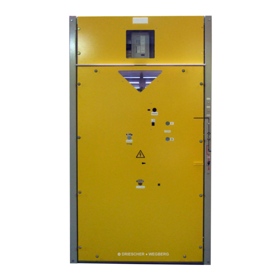
Page 14: Übersicht
11. Beschriftungsschild 11. label 12. Kurzschlussanzeiger (Option) 12. short circuit indicator (option) 13. Messbuchsen mit Schutzstöpsel für kapazitive 13. measuring sockets with protective caps for Spannungsanzeige bzw. Phasenvergleich capacitive voltage indication and phase (Option) comparison (option) LDTM 12 – 24 kV... -
Page 15: Technische Daten
>40°C take care of the reduction berücksichtigen factors für 12kV Anlagen for rated voltage 12kV **** **** für 12kV Kabel- und Transformatorfeld for rated voltage 12kV cable cubicle and transformer cubicle ***** ***** LDTM 12 – 24 kV... -
Page 16: Hh-Sicherungseinsätze
60787 no definite information according to IEC 62271-105 keine eindeutigen Angaben nach IEC 62271-105 möglich. for the protection of transformers can be given. Please Bitte nehmen Sie Rücksprache mit der Fa. DRIESCHER. contact Messrs. Driescher. LDTM 12 – 24 kV... -
Page 17: Abmessungen Und Gewichte
For more details, please contact Firma Driescher in Verbindung. Messrs. Driescher. Abmessungen Kabelanschluss / Dimensions cable connection Gewichte / weights Kabelschaltfeld / Cable cubicle 1142 ca. 145 kg Trafoschaltfeld / Transformer ca. 149 kg cubicle LDTM 12 – 24 kV... - Page 18 For more details, please contact Firma Driescher in Verbindung. Messrs. Driescher. Abmessungen Kabelanschluss / Dimensions cable connection Gewichte / weights Kabelschaltfeld / Cable cubicle 1142 ca. 195 kg Trafoschaltfeld / Transformer ca. 216 kg cubicle LDTM 12 – 24 kV...
-
Page 19: Montage
Use fixing means of the same length. The Der Winkel darf einen Wert von 90° nicht über- angle must not exceed a value of 90°. schreiten. Achten Sie auf gleichmäßige Gewichtsverteilung Pay attention to an equal weight balance! LDTM 12 – 24 kV... - Page 20 Beim Transport mit Gabelstapler oder Observe the centre of gravity of the Hubwagen Schwerpunkt Anlage switchgear during the transport with fork-lift beachten! or lift truck! Die Schaltanlage ist kopflastig! The switchgear is top-heavy! DRIESCHER • WEGBERG LDTM 12 – 24 kV...
-
Page 21: Aufstellen Der Schaltanlage
20 m betragen. 20 m, Stellen Sie die Schaltanlage nicht in explosions- the switchgear is not installed in rooms ex- gefährdete oder staubexplosionsgefährdete posed to an explosion risk or to a dust explo- Räume auf. sion risk. LDTM 12 – 24 kV... -
Page 22: Befestigung
Betonfundamenten oder horizontal concrete foundations or onto Zwischenrahmen mit ausreichender Trag- intermediate frames with a sufficient carry- festigkeit auf, um ein Verspannen der ing capacity to avoid the deformation of the Schaltfelder zu vermeiden. cubicles. LDTM 12 – 24 kV... -
Page 23: Aufstellungsempfehlungen
DRIESCHER • WEGBERG Aufstellungsempfehlungen Recommendations for the positioning LDTM-Schaltanlagen sind standardmäßig mit einem As a standard LDTM switchgears are equipped with Anti-Berst-System ausgerüstet, das eine raumunab- an Anti-Burst-System that enables a positioning in hängige Aufstellung ermöglicht. every location. Haben Sie eine Schaltanlage ohne Anti-Berst-... -
Page 24: Montage Der Sammelschienen
Klemmstelle busbar to the left clamping point of the busbar in the next cubicle. der Sammelschienen zur linken Klemmstelle der Sammelschienen im Nachbarschaltfeld. LDTM 12 – 24 kV... -
Page 25: Schaltanlage Erden
For earthings in switchgears with AC and Bemessungspannungen über 1kV, Mindest- for rated voltages higher than 1kV, see querschnitte und Strombelastbarkeit von VDE 0101 regarding minimum cross sec- Erdungsleitungen siehe VDE 0101. tions and current carrying capacity of earth- ing connections. LDTM 12 – 24 kV... -
Page 26: Aufstellen
Abstand zwischen dem Dach der the roof of the switchgear and the ceiling of Schaltanlage und der Stationsdecke min- the station is at least 50mm. destens 50mm beträgt. LDTM 12 – 24 kV... -
Page 27: Kuppeln Der Auslösewellen Des Anti-Berst-Systems Bei Einzelfeldlieferung
Coupling of the tripping shafts of the Berst-Systems bei Einzelfeldlieferung ABS when supplying single cubicles. LDTM–Schaltfelder mit Anti-Berst-System sind LDTM cubicles with an Anti-Burst-System are inter- untereinander mit je einer Kupplung versehen linked by one coupling each (Figure 3). (Bild 3). -
Page 28: Anschluss / Kabelanschluss
• • Kabelende nach Montageanweisung des Ka- Strip the cable end according to the assembly belgarnituren-Herstellers absetzen und Kabel- instructions of the cable producer and assemble garnitur montieren. the cable fitting. LDTM 12 – 24 kV... - Page 29 Tür unten links. placed behind the door at the bottom to the left. Zum Anschluss der Hilfsstromkreise beachten Sie To connect the auxiliary circuits please see the die mitgelieferten Schaltpläne. circuit diagrams included in our supply. LDTM 12 – 24 kV...
-
Page 30: Betrieb
Schaltkurbel für Erdungsschalter und Lasttrenn- operating crank for earthing switch and schalter switch-disconnector Spannungsanzeigegerät (Option) voltage indicating device (option) Antriebsabdeckung mit Warnschild (Option) cover for mechanism with warning plate (op- tion) Betriebsanleitung manual insulating protective plate (accessory) Einschubplatte (Zubehör) LDTM 12 – 24 kV... -
Page 31: Bedienung
Drehen Sie die Schaltkurbel gegen den Uhrzei- Turn the crank anticlockwise to its end position gersinn bis zum hörbaren Einrasten in die End- until it clicks audibly. stellung. The switch is ready again for operation Der Schalter ist einschaltbereit. LDTM 12 – 24 kV... - Page 32 Sichern gegen Wiedereinschalten Safeguarding against reclosing Antriebsabdeckung mit Warnschild (Option) am Apply the mechanism cover with warning plate Haltepunkt einhängen und die Antriebsöffnung ab- (optional) onto holding point and cover the mecha- decken. nism opening. LDTM 12 – 24 kV...
-
Page 33: Schalten Des Erdungsschalters
(risk of abziehen! Bei Verwendung von zwei injury)! Schaltkurbeln darf niemals gleichzeitig With the use of two switch cranks, one shall eine Schaltkurbel im Antrieb stecken blei- never remain inserted in the mechanism. ben. LDTM 12 – 24 kV... -
Page 34: Austausch Der Hh-Sicherungseinsätze
Verschließen Sie die Tür. Lock the door. Schalten Sie den Erdungs- Switch OFF the earthing schalter aus. switch. Schalten Sie den Lasttrenn- Switch ON the switch- schalter des Sicherungsfel- disconnector in the fuse des ein. cubicle. LDTM 12 – 24 kV... -
Page 35: Kabelprüfung
⇒ Tür schließen ⇒ Close the door ⇒ Einschubplatte entfernen ⇒ Remove the insulating protective plate Kabelabgang ist nun wieder für eine Inbetriebnahme Now the outgoing cable is ready again for setting to vorbereitet. work. LDTM 12 – 24 kV... -
Page 36: Maßnahmen Nach Auslösung Des Anti-Berst-Sensors
For this scope insert the insulating plate schen Oberblende und Türe ein- completely from top and angled into the führen und ganz einschieben (Mar- slot between the upper cover and the door kierung beachten) (observe the marking). LDTM 12 – 24 kV... -
Page 37: Optionale Ausstattung
Damage of the Switchgear is possible! sem Grund ist es erforderlich, vor der Therefore it is necessary to check the posi- ersten Inbetriebnahme die Positionierung tion of the limit switches before 1 commis- der Endschalter zu überprüfen. sioning. LDTM 12 – 24 kV... -
Page 38: Notentriegelung
Motorantriebes am jeweiligen Schaltfeld. mechanism in the relevant cubicle. Die Schaltvorgänge erfolgen dann wie bei einem The switching operations are then performed like handbetätigten Schalter. manual switch operation. LDTM 12 – 24 kV... -
Page 39: Stromlaufplan Motorantrieb
Resistances R1-R4 only at 220VDC. Legende/legend Umschalter selector switch Fern/vor Ort remote/local Taster AUS push button OFF Taster EIN push button ON Endschalter AUS limit switch OFF Endschalter EIN limit switch ON Erderverriegelung earthing switch interlocking LDTM 12 – 24 kV... -
Page 40: Magnetauslöser (Option)
Lasttrennschalters öffnet. switch is switched OFF, Bei DC Anwendung werden zusätzlich ein Hilfs- With DC applications, a second auxiliary switch schalter und ein Entstörkondensator verwendet. and a suppression capacitor are additionally used. LDTM 12 – 24 kV... -
Page 41: Kurzschlussanzeiger / Erdschlussanzeiger (Option)
Dabei werden die Grundsätze für support. Here the basic engineering principles for die Planung der Instandhaltung durch den Netzbe- the maintenance schedules are specified by the treiber vorgegeben. system user. LDTM 12 – 24 kV... -
Page 42: Wartungs- Und Inspektionsanleitung
Unabhängig vom verwendeten Anlagentyp sollte der Independent from the used switchgear type the Betreiber darauf achten, dass die Stationsräume operator should take care that the station rooms are sauber und trocken sind. clean and dry. LDTM 12 – 24 kV... -
Page 43: Austausch Von Bauteilen
• silver (contacts) • Gießharz auf Epoxidharzbasis (Stützer) • cast resin on epoxy resin base (insulators) • Kunststoffe (Schaltkammern und Trennwände) • plastics (arcing chambers and partition walls) Gefahrstoffe sind nicht vorhanden. Dangerous substances do not exist. LDTM 12 – 24 kV... -
Page 44: Prüfen Der Schaltanlage
Einhaltung der in den elektrotechnischen Regeln the observance of the limit values specified in the vorgegebenen Grenzwerte! electro technical regulations! Beachten Sie die Herstellerbedingungen für Span- Observe the instructions for the voltage indicators, nungsanzeigegeräte! issued by the manufacturer! LDTM 12 – 24 kV... -
Page 45: Fehlerbehebung
Cubicle door Locking between Schaltfeldtür lässt zwischen Er- Anschließend earthing switch. cannot be earthing switch sich nicht öffnen. dungsschalter lässt sich die Then the door opened. and cubicle door. und Schaltfeldtür. Schaltfeldtür can be opened. öffnen. LDTM 12 – 24 kV... -
Page 46: Anhang A
Kabel- the cable duct. kanal erfolgen. For any other mounting position the manufacturer Bei anderen hiervon abweichenden Aufstellungsge- has to be asked. gebenheiten muss der Hersteller befragt werden. LDTM 12 – 24 kV...
Need help?
Do you have a question about the LDTM and is the answer not in the manual?
Questions and answers