Advertisement
Quick Links
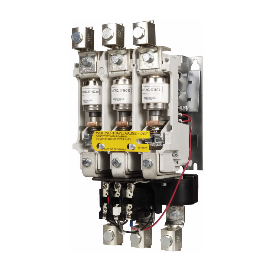
Instructions for V200, V210
540 Ampere, 3 Pole Vacuum Motor
Controller Nonreversing or Reversing
Fig. 1 V200 Motor Controller
(Type B Overload Relay shown)
7.00
6.75
Fig. 3 Dimension Drawing (Dimensions in inches)
Fig. 2 Left Portion of V210 Reversing Contactor
THE CONTROLLER
The V200 or V210 motor controller, when wired as shown
in Figure 5 or Figure 6, will operate as a full voltage starter
and will give protection against overload, but not against short-
circuit currents, when wired and provided with overload relay
(OLR) heaters as listed in the heater selection table or when
used with any means of inherent protection activated by motor
temperature.
The controller should be protected against short circuits by
providing branch circuit protection, in accordance with the
National Electrical Code (NEC).
This industrial type control is designed to be installed,
14.00
8.75
RoHS
16.23
I.L. 17089
Model A or B
Rev 01
Advertisement

Related Manuals for Eaton V200


Summary of Contents for Eaton V200
- Page 1 Fig. 2 Left Portion of V210 Reversing Contactor THE CONTROLLER The V200 or V210 motor controller, when wired as shown in Figure 5 or Figure 6, will operate as a full voltage starter and will give protection against overload, but not against short-...
- Page 2 V200, V210, 540 AMPERE VACUUM MOTOR CONTROLLER I.L. 17089 TYPE A OVERLOAD RELAY (See Figure 4) † CONTROLLER RATINGS THREE-PHASE HORSEPOWER AT The V200 motor controller can be equipped with a Type A Block type non-ambient compensated overload relay (unmarked 200V 230V 380V 460V...
- Page 3 220-240 VAC The Type GCO current transformers were specially 440-480 VAC designed to mount on A200 and V200 controllers and 550-600 VAC operate the Types A or B thermal overload relays. The 600/5 ratio Type GCP transformers have a single...
- Page 4 V200, V210, 540 AMPERE VACUUM MOTOR CONTROLLER I.L. 17089 TABLE VI - POWER CIRCUIT TERMINALS before the magnet seals. When the contactor is fully sealed closed, there should still be a small Lugs Wire Size amount of travel remaining for the plungers. See L63 Auxiliary Contact Adjustment.
- Page 5 GENERAL CONTACT WEAR ALLOWANCE The contactor portion of a V200 or V210 controller Contact material vaporizes from the contact faces (see Figure 7) has its main contacts sealed inside during every interruption and condenses inside the ceramic tubes from which all air has been evacuated, bottle.
-
Page 6: Maintenance
V200, V210, 540 AMPERE VACUUM MOTOR CONTROLLER I.L. 17089 If the controller is checked in its cabinet, make cer- tain that the contactor coil is electrically isolated, to pre- vent feedback into a control transformer that could be hazardous. Connect a separate power source of correct AC volt- age to the coil of the contactor. - Page 7 If the gap is too small, the hold winding will be 5. Lift the line side of the frame subassembly away inserted too soon, reducing the force to “hold” before the Fig. 8 Contactor Portion of a V200 Motor Controller...
- Page 8 In a particular contactor, the .34” The V200 or V210 motor controller is intended to be gap may need slight adjustment to avoid these problems. The key is not the measurement, but the performance of protected by power fuses and/or a circuit breaker in the magnet.
Need help?
Do you have a question about the V200 and is the answer not in the manual?
Questions and answers