
Related Manuals for Eaton EVER-Tap


Summary of Contents for Eaton EVER-Tap
- Page 1 COOPER POWER Voltage Regulators SERIES Effective June 2020 MN225008EN Supersedes February 2017 VR-32 and EVER-Tap™ Voltage Regulator Installation, Operation, and Maintenance Instructions...
- Page 2 CONTENTS OF THIS DOCUMENT SHALL NOT BECOME PART OF OR MODIFY ANY CONTRACT BETWEEN THE PARTIES. In no event will Eaton be responsible to the purchaser or user in contract, in tort (including negligence), strict liability or otherwise for any special, indirect, incidental or consequential damage or loss whatsoever, including but not limited to...
-
Page 3: Table Of Contents
Quik-Drive tap-changers ....23 EVER-Tap voltage regulator ....24 SAFETY FOR LIFE . -
Page 4: Safety For Life
FOR LIFE FOR LIFE Eaton meets or exceeds all applicable industry standards relating to product safety in its Cooper Power™ series products. We actively promote safe practices in the use and maintenance of our products through our service literature, instructional training programs, and the continuous efforts of all Eaton employees involved in product design, manufacture, marketing, and service. -
Page 5: Introduction
Cooper Power™ series VR-32 voltage regulator with the minimal precautions. Store the unit where the possibility of Quik-Drive™ tap-changer. It also contains this information mechanical damage is minimized. for the Eaton EVER-Tap™ voltage regulator with the VACUTAP™ RMV-SVR on-load tap-changer manufactured by WARNING Maschinenfabrik Reinhausen™. -
Page 6: Product Information
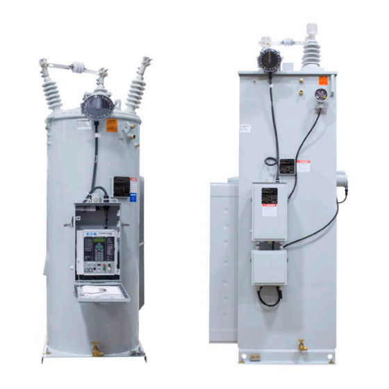
VR-32 and EVER-Tap™ Voltage Regulator Product information Description VR-32 and EVER-Tap single-phase step-voltage regulators from Eaton operate to keep voltage levels within programmed limits to improve power quality and are compatible with SCADA and automation distribution systems. Available in pole-, platform-, and pad-mounted and... - Page 7 Bolt-down provisions (4) Ground pad Substation base (available in units 167 kVA and above) Drain valve and insulating fluid sampling device Figure 2 . External features of the VR-32 and EVER-Tap voltage regulator InstallatIon, operatIon, and MaIntenance InstructIons MN225008EN June 2020...
-
Page 8: Installation
VR-32 and EVER-Tap™ Voltage Regulator Installation Systems connections WARNING Pre-installation inspection Hazardous Voltage . Connect the “S” bushing to Before connecting the regulator to the line, make the the source, the “L ” bushing to the load . For Wye following inspection: connections, connect the “SL ”... - Page 9 VR-32 and EVER-Tap™ Voltage Regulator Figure 5 . Regulating a three-phase, three-wire circuit with two regulators (Open Delta) Control Control Control Figure 6 . Regulating a three-phase, four-wire, multi-grounded wye (star) circuit with three regulators (Wye) Control Control Control Figure 7 . Regulating a three-phase, three-wire circuit with three regulators (Closed Delta)
-
Page 10: Nameplates
Various lengths of this information be verified prior to placing the control and rubber-coated control cables are available up to 120 feet regulator into service. When calling Eaton for service or (36.6 meters). support-related issues, have the catalog number and serial number found on the nameplate for reference. - Page 11 VR-32 and EVER-Tap™ Voltage Regulator Figure 9 . Typical nameplatee: international 50-Hz design InstallatIon, operatIon, and MaIntenance InstructIons MN225008EN June 2020...
-
Page 12: Placing Regulator Into Service
VR-32 and EVER-Tap™ Voltage Regulator Placing regulator into service of the regulator. Regulators can be placed into service without interrupting load continuity by installing bypass and disconnect switches. DANGER To perform an operational check and the switching Explosion Hazard . During bypass switching, the operations to install a regulator onto a system, use one of regulator must be in the neutral position . - Page 13 VR-32 and EVER-Tap™ Voltage Regulator Tap-position indication on the control at FC 12 displays 0 for neutral. Position indicator dial pointer is pointing directly at N or 0 for neutral. Measure the voltage difference between the S and L bushings using an approved voltmeter or the SAFE-TO-BYPASS feature on the CL-7 control.
- Page 14 VR-32 and EVER-Tap™ Voltage Regulator Setting the manual (hard) limit switches DANGER otee: Refer to “Position indicator and ADD-AMP Explosion Hazard . During bypass switching, the capability” on page 13 for a complete discussion regulator must be in the neutral position . Prior to of these features.
-
Page 15: Removal From Service
VR-32 and EVER-Tap™ Voltage Regulator Removal from service Verify the neutral position of the regulator using each of these four methods: Before removing a regulator from service, you must otee: Verify that the neutral indicator light on the return the regulator to neutral. Only a regulator in control is indicating the neutral position. -
Page 16: Construction And Operation
Construction and operation Drain valve with sampler . All regulators have a 1" drain valve with sampling device and a 1" upper filter press Eaton’s Cooper Power series VR-32 and EVER-Tap voltage connection. regulators are designed, manufactured, and tested in Hand-hole cover . -
Page 17: Position Indicator And Add-Amp Capability
Surge protection is provided when specified for regulators rated 438–668 A. Series arrester Table 2 . ADD-AMP adjustments All Eaton voltage regulators are equipped with a bypass arrester connected across the series winding between the Regulation (%) Current (%) source (S) and load (L) bushings. This arrester limits the ±... -
Page 18: Internal Construction And Wiring
The bridging reactor is a core-form design, consisting of a coil on each leg of one core. The inside half of one coil Eaton regulators are designed such that they can be partially is connected to the outside half of the other coil and vice... - Page 19 VR-32 and EVER-Tap™ Voltage Regulator Load Source C2 C1 CONTROL Figure 14 . Power circuit—series winding located on the source-side, ANSI ® Type B Source Load C2 C1 CONTROL Figure 15 . Power circuit—series winding located on the load-side, ANSI ® Type A...
- Page 20 VR-32 and EVER-Tap™ Voltage Regulator C2 C1 Load Source CONTROL Figure 16 . Power circuit – series auto transformer, Type AX (similar characteristics to Type A) C2 C1 Source Load CONTROL Figure 17 . Power circuit – series transformer, Type TX...
- Page 21 Eaton voltage regulators have provisions for operation at regardless of the power flow direction. The CL -7 control has system voltages other than the nominal rating, as listed full reverse power capabilities.
- Page 22 Table 4 provides the application information for the various CTs used on Eaton regulators. These CTs provide 200 mA output for the rated CT primary current. 167, 200...
-
Page 23: Quik-Drive Tap-Changers
VR-32 and EVER-Tap™ Voltage Regulator Quik-Drive tap-changers Eaton offers three Quik-Drive tap-changer models (see Figure 20, Figure 21, and Figure 22). Each device is sized for a specific range of current and voltage applications and share many similarities in their construction. The primary benefits of Quik-Drive tap-changers are: direct motor drive for simplicity and reliability;... - Page 24 VR-32 and EVER-Tap™ Voltage Regulator Quik-Drive tap-changer mechanism Contacts A tap change is initiated by the Control. After some rotation Several connection conditions are satisfied by the variety of the drive gear connected to the motor, a holding switch of contact structures. They are divided into arcing and energizes the motor through a separate circuit until the non-arcing.
-
Page 25: Ever-Tap™ Voltage Regulators
Operating sequence EVER-Tap™ voltage regulators When the tap-changer is in the neutral position and the The EVER-Tap voltage regulator utilizes a VACUTAP® control calls for a tap change, the following events occur. RMV-SVR-I-2000 tap changer from Maschinenfabrik Reinhausen (see Figure 23). This tap changer is rated for an The motor is energized and rotor begins to move. -
Page 26: Ever-Tap Important Operational Information
EVER-TAP controls and control boxes the ETMD-A is not compatible with Quik-Drive tap changers. Important information pertaining to a CL -7 control and control box equipped for use with and EVER-Tap voltage The CL-7 will trigger the actuator board to make a tap regulator: change. -
Page 27: Maintenance
It is also possible that the voltage supply and/or temperature are too low. EVER-Tap with motor drive unit ETMD-A CL-7 control settings CL-7 firmware version 1 .15 .0 or later is required on the ●... -
Page 28: Ever-Tap Voltage Regulator
● ● polymer version for the legacy QD8 tap-changer. Consult the document MN225077EN (expected release date Q4, 2020), EVER-Tap Voltage Regulator Maintenance Instructions and the inspection recommendations below for Holding switch details on maintenance procedures. Inspect for proper operation of the switch. -
Page 29: Operational Check
VR-32 and EVER-Tap™ Voltage Regulator Moveable contacts Duty Cycle Monitor (DCM) Run the tap-changer through all positions checking for This feature is not available for the EVER-Tap voltage ● ● proper alignment with stationary contacts. regulator. Replace excessively worn contacts. -
Page 30: Insulating Fluid Maintenance
The EVER-Tap voltage regulator is equipped with an arc Before collecting a sample, rinse the sampling bottle interrupter. The arc occurring during tapping operations ●... -
Page 31: Untanking The Regulator
VR-32 and EVER-Tap™ Voltage Regulator With the contact closed, auto operation will be inhibited. WARNING The CL -7 control will illuminate the Auto Tap Blocked LED and display Blockede: CL or Comm on the Metering-PLUS The lifting eyes on the top of the voltage regulator are Load Current screen. -
Page 32: Retanking The Regulator
VR-32 and EVER-Tap™ Voltage Regulator Retanking the regulator Steps for retanking: If the core and coil assembly have been out of oil for more than 4 hours, the coil must be dried, as follows: Bake the unit at 100˚C (212˚F) for 24 hours. -
Page 33: Spare Parts
Control Markings Function Ordering Information Load-Side PT When ordering replacement parts or field-installation Differential PT accessories for your Eaton voltage regulator, provide the CT Shorting Switch following information: CT + Regulator serial number (found on nameplate) CT + ● ●... -
Page 34: Voltage Regulator Ratio Test
VR-32 and EVER-Tap™ Voltage Regulator control is in the forward mode. Reversing the voltage WARNING source leads on the L and SL bushings should cause the control panel REVERSE POWER LED to illuminate, Hazardous Voltage . When troubleshooting energized indicating the control is in the reverse power flow equipment, protective gear must be worn to avoid mode. -
Page 35: Voltage Regulator Potential Transformer Ratio Test
VR-32 and EVER-Tap™ Voltage Regulator Connect a separate 120 Vac supply to the EXTERNAL otee: On a type B regulator, the difference between SOURCE terminals on the control front panel. Move the taps will be slightly less than calculated as the control power switch to the EXTERNAL position to the regulator is tapped toward 16 Lower. -
Page 36: Regulator Dry-Out Procedure
VR-32 and EVER-Tap™ Voltage Regulator Measure the voltage between the top of the V1 WARNING switch and the terminal strip ground marked G. The expected voltage should equal the measured voltage. Hazardous Voltage . The regulator tank must be solidly A significant difference between the expected and earth grounded . - Page 37 VR-32 and EVER-Tap™ Voltage Regulator position dependent on the type and rating of the WARNING regulator. Current reduces to zero when it reaches the neutral position. Hazardous Voltage . When troubleshooting energized equipment, protective gear must be worn to avoid personal contact with energized parts .
-
Page 38: Insulation Resistance Test
VR-32 and EVER-Tap™ Voltage Regulator Insulation resistance test Read the test value in mega-ohms; then compare the reading with the baseline reading: Purpose If the new reading is lower than the baseline ● ● The purpose of this procedure is to describe the proper... - Page 39 VR-32 and EVER-Tap™ Voltage Regulator Place the CONTROL FUNCTION switch on LOCAL MANUAL. 10. Jog the RAISE/LOWER switch in the direction the capacitive voltage was observed. This should allow the tap-changer to free itself. Using the RAISE/LOWER switch, run the tap-changer one or two steps. Inspect the position indicator to verify that the indicating pointer is directly over a tap position mark.
-
Page 40: Appendix
VR-32 and EVER-Tap™ Voltage Regulator Appendix Connections and voltage levels Table 9 . Tap connections & voltage levels (60 Hz) Table 9 . (continued) Nominal Ratio-Adjusting Data Nominal Ratio-Adjusting Data Regulator Single- Test Overall Regulator Single- Test Overall Voltage Phase Internal... - Page 41 VR-32 and EVER-Tap™ Voltage Regulator Table 10 . Tap connections & voltage levels (50 Hz) Regulator Nominal Ratio-Adjusting Data Test Overall Voltage Single-Phase Terminal Potential Rating Voltage Internal Tap PT Ratio RCT Tap Voltage Ratio 6600 6930 – 54.9:1 119.2 58.1:1 6600 –...
-
Page 42: Add-Amp Capabilities
172.5 416.3 55/65 °C rise rating on Eaton voltage regulators gives an additional 12% increase in capacity if the tap-changer’s maximum current rating has not been exceeded. For loading in excess of the above values, please refer to your Eaton representative. - Page 43 22000 33000 55/65 °C rise rating on Eaton voltage regulators gives an additional 12% increase in capacity if the tap-changer’s maximum current rating has not been exceeded. For loading in excess of the above values, please refer to your Eaton representative.
-
Page 44: Wiring Diagrams
VR-32 and EVER-Tap™ Voltage Regulator Wiring diagrams Figure 27 . Typical internal wiring of voltage regulators with a QD3 tap-changer InstallatIon, operatIon, and MaIntenance InstructIons MN225008EN June 2020... - Page 45 VR-32 and EVER-Tap™ Voltage Regulator Figure 28 . Typical internal wiring of voltage regulators with QD5 and QD8 tap-changers InstallatIon, operatIon, and MaIntenance InstructIons MN225008EN June 2020...
- Page 46 VR-32 and EVER-Tap™ Voltage Regulator Figure 29 . Typical internal wiring of EVER-Tap voltage regulator tap changer InstallatIon, operatIon, and MaIntenance InstructIons MN225008EN June 2020...
- Page 47 VR-32 and EVER-Tap™ Voltage Regulator POS-2 (BLK) POS-5 (ORG) POS-8 (WHT) POS-6 (RED/BLK) POS-7 (BLK) POS-4 (LT BLU/BLK) POS-3 (BLK/WHT) POS-10 (GRN/BLK) POS-9 (BLU) GROUND (WHT) COLOR CHART COLOR BLACK WHITE GREEN ORANGE BLUE A (GRN) CC (GRN) WHITE/BLACK RED/BLACK...
- Page 48 VR-32 and EVER-Tap™ Voltage Regulator RS-1 (ORG/BLK) CC (ORG/BLK) CC (RED) CC (BLK) RLS-2 (BLU) JUNCTION BOX POSITION INDICATOR TERMINAL BOARD CC (WHT/BLK) (JBB) JBB-L (GRN/BLK) LOWER LIMIT SWITCH (LLS) CC (GRN/BLK) (RED) JBB-R (BLU) RAISE LIMIT CC (BLU/BLK) SWITCH (RLS)
- Page 49 VR-32 and EVER-Tap™ Voltage Regulator CONTROL CABLE (CC) MOTOR CC (BLU/BLK) CAPACITOR CC (BLK/WHT) (NOTE 2) (NOTE 1) 10 (BLK) NOTES 1. LEAD 20 (WHT/BRN) CONNECTS V6-4 TO V7 INSTEAD OF VS TO V7 WHEN A DIFFERENTIAL PT IS UTILIZED.
- Page 50 (CC) BOARD HARNESS (AB) BRAKING AB (RED/WHT) CAPACITOR AB (BLU/WHT) AB (RED/WHT) MOTOR CC (RED/WHT) CAPACITOR AB (GRN/WHT) CC (GRN/WHT) 10 (BLK) AB (WHT) Figure 33 . EVER-Tap back panel signal circuit InstallatIon, operatIon, and MaIntenance InstructIons MN225008EN June 2020...
- Page 51 VR-32 and EVER-Tap™ Voltage Regulator his page is intentionally left blank. InstallatIon, operatIon, and MaIntenance InstructIons MN225008EN June 2020...
- Page 52 United States Eaton.com/cooperpowerseries © 2020 Eaton All Rights Reserved Eaton is a registered trademark. Printed in USA For Eaton‘s Cooper Power series product Publication No. MN225008EN information call 1-877-277-4636 or visit: All trademarks are property www.eaton.com/cooperpowerseries. June 2020 of their respective owners.
Need help?
Do you have a question about the EVER-Tap and is the answer not in the manual?
Questions and answers