Sign In
Upload
Manuals
Brands
SICK Manuals
Media Converter
ATM 60-C Series
User Manuals: SICK ATM 60-C Series Absolute Encoder
Manuals and User Guides for SICK ATM 60-C Series Absolute Encoder. We have
1
SICK ATM 60-C Series Absolute Encoder manual available for free PDF download: Commissioning Instructions
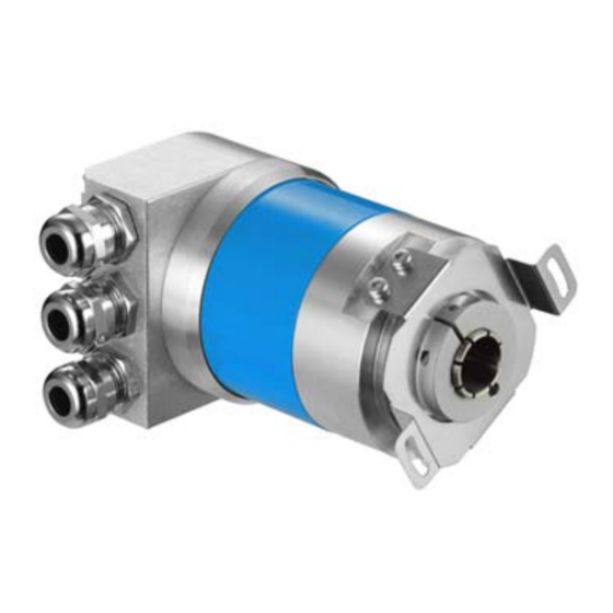
SICK ATM 60-C Series Commissioning Instructions (64 pages)
Absolute rotary encoder with CANopen Interface to communications interface DS 301 V 4.0 and device profile DSP 406 V 2.0
Brand:
SICK
| Category:
Media Converter
| Size: 0 MB
Table of Contents
Table of Contents
3
1 Explanation of Symbols
6
2 Abbreviations Used
6
3 Safety Advice
7
4 Introduction
8
CAN General
8
CAN Application Layer (CAL)
8
Canopen
8
Canopen Communications Profile
8
Canopen Device Profiles
9
5 Communications Model
10
Process Data Objects (PDO)
10
Service Data Objects (Sdos)
11
Network Management Objects
12
Services to Control the Nodes
12
Start Remote Node
12
Stop Remote Node
12
Enter Pre-Operational
12
Reset Node
13
Reset Communication
13
Error Control Services
13
Boot-Up Service
13
Synchronization Object (Sync Object)
13
Emergency Object (Emcy Object)
13
6 Network Management
14
Node Monitoring
14
Node Guarding Protocol
14
Heartbeat Protocol
15
Synchronization
17
7 Initialization and System Boot-Up
17
Initialization
17
Boot-Up
19
Identifier Allocation
19
Predefined Connection Set
19
8 EDS File
20
9 Object Directory of the Encoder
21
Object Directory of the Communications Profiles
21
Description of the Individual Objects
22
Object 1000 Hex: Device Type
22
Object 1001 Hex: Error Register
23
Object 1003 Hex: Predefined Error Field
23
Object 1005 Hex: COB-ID for SYNC Messages
23
Object 1008 Hex: Manufacturer's Device Name
24
Object 1009 Hex: Manufacturer's Hardware Version
24
Object 100A Hex: Manufacturer's Software Version
24
Object 100C Hex: Guard Time and 100D Hex: Lifetime Factor
24
Object 1010 Hex: Save Parameters
25
Object 1011 Hex: Load Default Parameters
26
Object 1014 Hex: COB-ID for Emergency Message
27
Object 1015 Hex: Inhibit Time for Emergency Message
28
Object 1017 Hex: Producer Heartbeat Time
28
Object 1800 Hex: Transmit PDO 1, Parameter
28
Object 1802 Hex: Transmit PDO 2, Parameter
30
Object 1A00 Hex: Transmit PDO 1, Mapping
30
Object 1A02 Hex: Transmit PDO 2, Mapping
31
Object Directory for the Device Profile
32
Description of the Individual Objects
34
Object 6000 Hex: Operating Parameters
34
Object 6001 Hex: Measuring Steps Per Revolution
34
Object 6002 Hex: Total Number of Measuring Steps
34
Object 6003 Hex: Preset Value
35
Object 6004 Hex: Position Value
35
Object 6200 Hex: Cycle Timer
35
Object 6300 Hex: Cams Status Register
36
Object 6301 Hex: Cams, Enable Register
36
Object 6302 Hex: Cams, Polarity Register
37
Object 6310 to 6317 Hex: Cams 1
37
Object 6320 to 6327 Hex: Cams 1
37
Object 6330 to 6337 Hex: Cams 1
38
Object 6400 Hex: Working Range, Status Register
38
Object 6401 Hex: Working Range, Lower Limit
38
Object 6402 Hex: Working Range, Upper Limit
39
Object 6500 Hex: Operating Status
39
Object 6501 Hex: Single-Turn Resolution (Physical)
39
Object 6502 Hex: Number of Revolutions (Physical)
39
Object 6503 Hex: Alarms
39
Object 6504 Hex: Alarms Supported
40
Object 6505 Hex: Warnings
40
Object 6506 Hex: Warnings Supported
41
Object 6507 Hex: Profile and Software Version
41
Object 6509 Hex: Operating Time
42
Object 6509 Hex: Offset Value
42
Object 650A Hex: Manufacturer-Specific Offset Value
42
Object 650B Hex: Serial Number
42
Object Directory for the Manufacturer-Specific Area
42
Description of the Individual Objects
43
Object 2000 Hex: Source for Node ID
43
Object 2001 Hex: Node ID
43
Object 2002 Hex: Baud Rate
43
Object 2003 Hex: Format for Speed and Acceleration
44
Object 2004 Hex: Speed
44
Object 2005 Hex: Acceleration
44
Object 2006 Hex: Change of State
45
10 Function of the Cams
45
11 Technical Description
47
General
47
Features
47
Technical Data
48
12 Connecting the Encoder
49
Setting the Node ID
49
Setting the Baud Rate
50
Setting the Bus Termination
50
Preset Function
50
Screening
51
Screening Rules
51
Pin Allocation
52
Bus Connector with PG Screw Fittings
52
Bus Connector with 5-Pole Micro Circular Plug Connectors
53
Status LED
53
13 Commissioning
54
Switch on Encoder
54
Configure Encoder
55
Example of PDO Mapping
55
Example of Changing the Object "Measuring Steps Per Revolution
55
Write All Objects into EEPROM
56
Load All Objects with Default Values
56
EDS File
57
14 Dimensional Drawing
58
15 Scope of Supply
60
16 Ordering Information
60
17 Notes
62
Advertisement
Advertisement
Related Products
SICK ATM60 SSI
SICK ATM60-C4H13X13
SICK ATM60-C1H13X13
SICK ATM60-CAH13X13
SICK AFS60 PROFINET
SICK AFM60S Pro
SICK AHS36 CANopen Inox
SICK AFS60 S01
SICK AFM60 S01
SICK AFM60 S02
SICK Categories
Accessories
Security Sensors
Measuring Instruments
Scanner
Barcode Reader
More SICK Manuals
Login
Sign In
OR
Sign in with Facebook
Sign in with Google
Upload manual
Upload from disk
Upload from URL