Advertisement
Quick Links
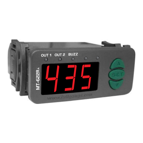
1 - DESCRIPTION
MT-622Ri is a temperature controller that uses a J type thermocouple sensor; it has two outputs for
temperature control and an internal audible alarm. It also has a timer that can operate in different modes,
triggered by digital inputs, which indicates the end time of one or two processes.
The first stage can use a cyclic preheating mode, and the second stage may operate as an alarm, cyclic
timer or indication of the end of a process. You can also use 5 configurable formulas, which allow one to
quickly change the values of the setpoint temperature and the hysteresis of the first stage and the
process time.
2 - APPLICATIONS
• Fryers
• Ovens
3 - TECHNICAL SPECIFICATIONS
- Power supply: MT-622Ri - 115/230 Vac ±10% (50/60 Hz)
MT-622RiL - 12/24 Vac/dc
- Temperature control: -50 to 600°C/ -58 to 999°F
- Resolution: 1ºC/1ºF
- Dimensions: 71 x 28 x 71 mm
- Operating temperature: 0 to 50ºC/32 to 122ºF
- Operating humidity: 10 to 90% RH (non-condensing)
- Current per output: OUT 1 - 16 (8) A/250 VAC 1HP - 4000W
OUT 2 - 5 (3) A/250 VAC 1/8HP
- Sensor: J type Thermocouple (sold separately)
4 - SETTINGS
4.1 - Adjust the control temperature (SETPOINT) and process
time.
If it is configured not to use formulas (F03 = 0):
- Press and hold the @ key for two seconds, until the message [SEt] appears;
- Then the message [SP1] will appear and it will be possible to adjust the stage 1 setpoint;
- Use the keys > and < to change the value, and press @ to confirm.
It will then be possible to adjust the setpoint of stage 2 [SP2] and the process time ( [TMR] ).
Note: The adjustment of the stage 2 setpoint can only be configured if the unit is set to operate as a
thermostat (F29 = 0 or 1).
If it is set to use formulas (F03 = 1):
Each formula can be configured to use different values for the setpoint, hysteresis of stage 1 and
the time of the process. To select the formula:
- Press and hold the @ key for two seconds, until the message [SEt] and [Sp1] appears;
- You will then see the currently selected formula.
- Use the > or < keys to select which of the 5 formulas will be used:
[rc1] - Formula 1;
[rc2] - Formula 2;
[rc3] - Formula 3;
[rc4] - Formula 4;
[rc5] - Formula 5.
To confirm the selection, press @.
Then one can adjust the setpoint of stage 2 [SP2], if configured to operate as a thermostat (F29 =
0 or 1).
Note: The values of the functions of each formula are configured in the parameter menu.
4.2 - Changing Parameters
- Access the F01 function by simultaneously pressing the > and < keys for 2 seconds until [fun]
appears, then release. [F01] will then appear, press @ (short press).
- Use the > or < keys to enter the access code (123) and, when ready, press @.
- Use the > or < keys to access the desired function.
- After selecting the function, press @ (short press) to display the value configured for that function.
- Use the > or < keys to change the value, and when ready, press @ to store the configured
value and return to the function menu.
- To exit the menu and return to normal operation (temperature indication) press @ (long press) until
[---] appears.
4.3 - Table of parameters
Fun
Description
F01
Access Code (123)
F02
Indicator Offset (offset)
F03
Using formulas in the 1st stage
F04
Operation Setpoint of the 1st stage (rc1)
F05
Operation Setpoint of the 1st stage (rc2)
F06
Operation Setpoint of the 1st stage (rc3)
F07
Operation Setpoint of the 1st stage (rc4)
F08
Operation Setpoint of the 1st stage (rc5)
F09
Differential control of the 1st stage (rc1) (*)
F10
Differential control of the 1st stage (rc2)
F11
Differential control of the 1st stage (rc3)
F12
Differential control of the 1st stage (rc4)
F13
Differential control of the 1st stage (rc5)
F14
Process time (rc1)
F15
Process time (rc2)
F16
Process time (rc3)
MT-622Ri
TWO STAGE DIGITAL CONTROLLER
WITH ALARM AND CYCLIC TIMER
AND PROCESS TIMER
Ver.02
CELSIUS
FAHRENHEIT
Min Max
Min Max
Unit
Standard
Unit
-
-
-
-
-
-
-
-10
10
-
0
-18
18
-
0
1
-
0
0
1
-
-50
600
°C
-50
-58
999
°F
-50
600
°C
-50
-58
999
°F
-50
600
°C
-50
-58
999
°F
-50
600
°C
-50
-58
999
°F
-50
600
°C
-50
-58
999
°F
1
40
°C
1
1
104
°F
1
40
°C
1
1
104
°F
1
40
°C
1
1
104
°F
1
40
°C
1
1
104
°F
1
40
°C
1
1
104
°F
1
999
sec./min.
5
1
999
sec./min.
1
999
sec./min.
5
1
999
sec./min.
1
999
sec./min.
5
1
999
sec./min.
F17
Process time (rc4)
F18
Process time (rc5)
F19
Timebase of the Timer
F20
Operational Mode of the 1st stage
F21
Minimum setpoint allowed to the end user (1st stage)
F22
Maximum setpoint allowed to the end user (1st stage)
F23
Minimum delay to re-connect the output of the 1st stage
F24
Temperature to terminate preheating
F25
Time base used to preheat
F26
Time that preheating is connected
F27
Time that preheating is disconnected
F28
Maximum cycling time (if F20 = 2)
F29
Operational Mode of the 2nd stage
F30
Minimum setpoint allowed to the end user (2nd stage)
F31
Maximum setpoint allowed to the end user (2nd stage)
F32
Control differential (hysteresis) of the 2nd stage
F33
Minimum delay to re-connect the output of the 2nd stage
F34
Alarm disability time when turning the controller on
F35
Time the ALARM/TIMER is on
F36
Time ALARM/TIMER is off
F37
Time to reactivate the alarm when manually disabled
F38
Timebase of cyclical timer
F39
Time for activation of 2nd stage cyclic timer
F40
Operation Mode of audible alarm
F41
Activation point of audible alarm (lower limit)
F42
Activation point of audible alarm (upper limit)
F43
Time audible alarm is connected
F44
Time audible alarm is disconnected
F45
Audible alarm disability time when turning the controller on
F46
Time to reactivate the audible alarm when manually disabled
F47
Enabling and viewing mode of the process timer
F48
Audible alert at the end of the process (Buzzer)
F49
Operational mode of digital inputs
F50
Intensity of the digital filter
4.4 - Description of parameters
F01 - Access Code
This is necessary when you want to change the configuration parameters. It is not necessary to insert
this code to see the set parameters.
F02 - Indicator Offset (offset)
Allows the compensation of eventual deviations in temperature reading, caused by the change of the
sensor or changing the length of the cable.
F03 - Using formulas in the 1st stage
Allows one to configure the controller in order to use the formulas or not:
[,0,] - No: If setup this way, the instrument will not use the receipt values in the control routines. For
this, setpoint 1 [SP1] will be used and process time [tmr], which are adjusted through the easy
access menu. The differential control to be used will be the same as formula 1, [F09] "Differential
control of the 1st stage (rc1)."
The value set in [sp1] can be set between [F21] "Minimum setpoint allowed to the end user (1st
stage)" and [F22] "Maximum setpoint allowed to the end user (1st stage)."
[,1,] - Yes: If configured this way, the instrument uses the control routines of the setpoint values,
differential control and process time of the formula that is active.
The formula selection will be made through the easy access menu, in the same way as adjusting the
setpoint. However, the value shown on the display will be the name of the formula that is active.
Example: [Rc1]
F04 - Operation setpoint for the 1st stage (rc1)
F05 - Operation setpoint for the 1st stage (rc2)
F06 - Operation setpoint for the 1st stage (rc3)
F07 - Operation setpoint for the 1st stage (rc4)
F08 - Operation setpoint for the 1st stage (rc5)
Standard
These parameters specify the desired temperature for each formula in the 1st stage.
-
F09 - Differential control of the 1st stage (rc1) (*)
0
F10 - Differential control of the 1st stage (rc2)
0
F11 - Differential control of the 1st stage (rc3)
-58
F12 - Differential control of the 1st stage (rc4)
-58
F13 - Differential control of the 1st stage (rc5)
These parameters specify the desired temperature for each formula in the 1st stage.
-58
-58
(*) The function F09 is used when F03 = 0 together with [SP1] or when F03 = 1 in combination with
-58
setpoint [rc1].
2
F14 - Process Time (rc1)
2
F15 - Process Time (rc2)
2
F16 - Process Time (rc3)
2
F17 - Process Time (rc4)
2
F18 - Process Time (rc5)
These parameters specify the duration of the process for each formula.
5
5
5
1
999
sec./min.
5
1
999
sec./min.
1
999
sec./min.
5
1
999
sec./min.
0
1
-
1
0
1
-
0
2
-
1
0
2
-
-50
600
°C
-50
-58
999
°F
-50
600
°C
600
-58
999
°F
0
999
sec.
0
0
999
sec.
-50
600
°C
60
-58
999
°F
0
3
-
0
0
3
-
1
999
sec./min.
1
1
999
sec./min.
1
999
sec./min.
1
1
999
sec./min.
1
999
min.
5
1
999
min.
0
10
-
1
0
10
-
-50
600
°C
-50
-58
999
°F
-50
600
°C
600
-58
999
°F
20
°C
1
1
1
36
°F
0
999
sec.
0
999
sec.
0
min.
0
999
0
0
999
min.
1
999
sec./min.
1
sec./min.
1
999
999
999
sec./min.
sec./min.
0
1
0
[Aut]
999
[Aut]
[Aut]
999
min.
min.
0
0
0
3
3
-
-
0
5
0
999
999
sec.
sec.
0
1
0
2
-
2
-
-50
-50
-58
600
°C
999
°F
-50
600
600
-58
999
°C
°F
0
999
sec.
1
0
999
sec.
999
sec.
999
sec.
0
1
0
min.
0
999
min.
0
0
999
[Aut]
[Aut]
[Aut]
999
min.
999
min.
0
2
0
-
-
2
2
0
1
0
-
-
1
1
0
0
0
3
-
3
-
0
0
0
-
-
9
9
5
5
1
1
-58
999
0
140
0
1
1
5
1
-58
999
2
0
0
1
1
[Aut]
0
5
1
-58
999
1
1
0
[Aut]
2
1
0
0
Advertisement

Related Manuals for Full Gauge Controls MT-622Ri


Summary of Contents for Full Gauge Controls MT-622Ri
- Page 1 Process time (rc4) 1 - DESCRIPTION MT-622Ri is a temperature controller that uses a J type thermocouple sensor; it has two outputs for sec./min. sec./min. Process time (rc5) temperature control and an internal audible alarm. It also has a timer that can operate in different modes, Timebase of the Timer triggered by digital inputs, which indicates the end time of one or two processes.
- Page 2 F19 - Timebase of the Timer as an alarm or timer. To always keep the alarm triggered, just set "0" in this function. Allows one to select which time base will be used to count the processing time [,0,] - Seconds F37 - Time to reactivate the alarm when manually disabled [,1,] - Minutes This function sets the manual disability of the alarm.
- Page 3 To end process 2 before the set time, press DIG2 again. The message [en2] will be shown on the If timer 1 is operating and the digital input 1 (DIG1) key is pressed the message [en1] will be display intermittently for 2 seconds. shown on the display and this will stop timer 1.
- Page 4 Power supply Dimension of the clipping Install a magnetic contactor when for setting of the instrument exceeding the specified current. OUT 2 common in panel 72 mm MT-622Ri MT-622RiL *Sensor sold separately 7 - 8 115V 230V 7 - 9 IMPORTANT...
Need help?
Do you have a question about the MT-622Ri and is the answer not in the manual?
Questions and answers