
Related Manuals for Lamtec ETAMATIC


Summary of Contents for Lamtec ETAMATIC
- Page 1 Quick Reference for Endusers ETAMATIC / ETAMATIC S Sensors and Systems for Combustion Engineering www.lamtec.de...
-
Page 3: Table Of Contents
Table of Contents Table of Contents General Information ............3 Validity of these Instructions . -
Page 4: General Information
General Information Validity of these Instructions This manual is valid for the ETAMATIC ETAMATIC S in any configuration. The content of this document refers to software version v5.8. Other software versions may cause that some of the functions described in this document are not available or have another functionality as described in this document. -
Page 5: Safety
Safety Safety For Your Safety The following symbols are used in this document to draw the user's attention to important safe- ty information. They are located at points where the information is required. It is essential that the safety information is observed and followed, and that applies particularly to the warnings. DANGER! This draws the user's attention to imminent danger. -
Page 6: Brief Description
Brief Description Brief Description The ETAMATIC regulates up to 4 control elements as a function of a control variable, in ac- cordance with freely programmable curves. The ETAMATIC has 4 three-point step control out- puts. The ETAMATIC S has 3 three-point step control outputs and one 4-20 mA output. -
Page 7: Operating Description
The ETAMATIC then interrogates the boiler safety interlock chain (ETAMATIC) or the common safety interlock chain (ETAMATIC) and the contact of the air pressure monitor. If it does not detect an "OK" condition, the text of a corresponding message appears and the operating con- trol stops. -
Page 8: Fault
Press keys 3 and 2 to browse through the fault history. NOTICE If it is certain that the ETAMATIC has carried a voltage at all times since the last fault, it is pos- sible, that from the present output of the running time counter and the current time, to deter-... -
Page 9: Operation
Manual resetting of O fault is possible at any time, as follows: Press key RESET ETAMATIC in O trim mode If not, switch over to O trim mode Press key 15 M once... -
Page 10: Calling Fault History O Trim
30 sec are stored. They are only stored in the EEPROM once the fault is cleared up or the ETAMATIC leaves the operating mode or control or base firing rate. 6.1.4 Calling CO/O... -
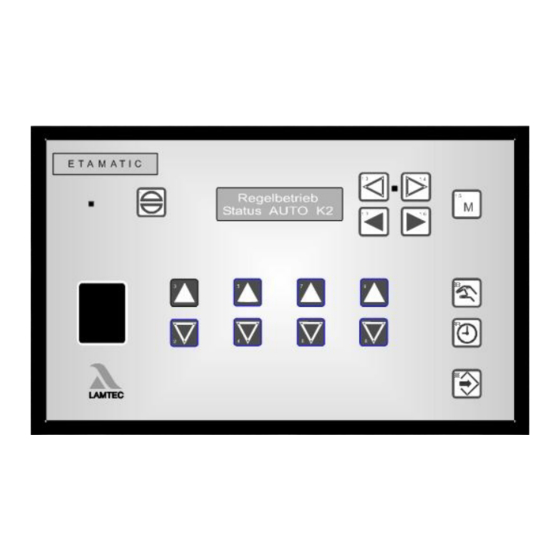
Page 11: Display And Interpretation Of The Operating Modes
Operation I - O actual value II - CO value Edge position: "-" Air would be reduced "+" Air would be increased 11 11 optimisation steps have taken place big "C" means optimisation dur- ing increasing firing rate small "c"... -
Page 12: Displaying The Running Time Meter
NOTICE The total counter refers to the ETAMATIC 's running time. It starts timing as soon as the unit is connected to a voltage source (this also provides the basis for the fault history). The individual running time counters refer to the burner's running time. They start timing as... -
Page 13: Calling The Checksums
Press key 11 ENTER again. In the ETAMATIC without pilot burner, the 2 safety time includes the safety time. The 1 safety time figure is then irrelevant. If you have changed parameters, reset the ETAMATIC. Only a reset refreshes a checksum. -
Page 14: Internal Burner Firing Rate Controller
Moving Screen "Actual Temperature is too high" By pressing the HAND key, the ETAMATIC would still starts as long as the maximum temperature is not exceeded. -
Page 15: Manual Control
Press key MANUAL again to cancel firing rate controller. It is also possible to switch the ETAMATIC to "Manual Control" with the terminals. By short- circuiting the Pt100 signal (e.g. bridge terminal 19 and 20) the burner firing rate controller is switched off. -
Page 16: Appendix
Description → READY (signal on terminal 58) ZÜ → IGNITION POSITION or IGNITION → SETTING/IGNITION position (same as IGNITION, but ETAMATIC on SETTING) → BASE FIRING RATE → SETTING/BASE FIRING RATE” (as BASIC FIRING RATE, but ETA- MATIC on SETTING) →... -
Page 17: Fault Codes
Appendix Fault Codes NOTICE The LAMTEC burner controls use different methods to detect fault messages between main processor and watchdog processor: BT300/ETAMATIC/FMS/VMS/FA1: The bus transmission does not generally use different fault numbers to distinguish between watchdog processor and main processor faults. In order to distinguish the main processor fault messages from the watchdog processor fault messages, an offset of 10000 is added to the watchdog processor faults. - Page 18 Appendix Fault Restart according to Description Code EN676 1st monitoring band over range too long. Channel: 3 1st monitoring band over range too long. Channel: 4 1st monitoring band under range too long. Channel: 1 1st monitoring band under range too long. Channel: 2 1st monitoring band under range too long.
- Page 19 Appendix Fault Restart according to Description Code EN676 Leak check fault: gas pressure still applied. Leak check fault: gas pressure missing. Vent gas line manually. >88 Oil pressure < min !!! Gas > min appears in oil operation. Boiler safety chain dropping. Gas safety chain dropping.
- Page 20 Error in reference, channel: 3 Error in reference, channel: 4 Relay driver self-test : output terminal 11 or 66 (ETAMATIC) faulty. Relay driver self-test : output terminal 16 or 65 (ETAMATIC) faulty. Relay driver self-test : output terminal 43 or 68 (ETAMATIC) faulty.
-
Page 21: Calling Up The Condition Of The Digital Inputs
Appendix Calling Up the Condition of the Digital Inputs press keys 16 and 17 to switch to the digital inputs Significance of ETAMATIC digital input display signal is active signal is inactive only with ETAMATIC without front panel... - Page 22 LAMTEC SYSTEM BUS Communications interface Fig. 8-3 Rear view ETAMATIC NOTICE PC connection possible only via LAMTEC interface adapter! NOTICE For exchange of the fuses F3, F4, F5 these specifications are to be complied: - 2A slow blow - high breaking capacity according to IEC 60127-2, Sheet 5: 1500A @ 250VAC...
-
Page 23: Eu Declaration Of Conformity
Appendix EU Declaration of Conformity... - Page 24 Appendix...
- Page 25 Appendix...
- Page 26 The information in this publication is subject to technical changes. LAMTEC Meß- und Regeltechnik für Feuerungen GmbH & Co. KG Wiesenstraße 6 D-69190 Walldorf Telefon: +49 (0) 6227 6052-0 info@lamtec.de Telefax: +49 (0) 6227 6052-57 www.lamtec.de Printed in Germany | Copyright 2020...
Need help?
Do you have a question about the ETAMATIC and is the answer not in the manual?
Questions and answers