Lamtec ETAMATIC Manual
Hide thumbs
Also See for ETAMATIC:
- Manual (136 pages) ,
- Quick reference (62 pages) ,
- Quick reference (26 pages)

Related Manuals for Lamtec ETAMATIC


Summary of Contents for Lamtec ETAMATIC
- Page 1 Manual ETAMATIC / ETAMATIC S Sensors and Systems for Combustion Technology www.lamtec.de...
-
Page 3: Table Of Contents
Table of Contents Table of Contents General Information ............6 Validity of these Instructions. - Page 4 Table of Contents 5.2.5 Programming the 3rd up the 10th Point....... 31 5.2.6 Saving Curve .
- Page 5 9.13.3 LAMTEC SYSTEM BUS Plug ........
- Page 6 9.26 Technical Data ............141 9.27 ETAMATIC without internal flame monitoring....... . 145 9.28 Dimensions and Weight .
-
Page 7: General Information
General Information General Information Validity of these Instructions These instructions apply to the ETAMATIC and ETAMATIC S in any configuration. These devices conform to the following standards and regulations: • EN 230 • EN 267 (where applicable) • EN 298 •... -
Page 8: Variants - Device Configuration
The variant number describes the device's variant. You will find the variant number on the side of the housing. The variant number is based on the following key: Serial number Example: ETAMATIC in variant no.: 0 0 001 r0 AM S AP ETAMATIC a: Flame monitoring ... - Page 9 3x DPS and 1x continuous output, FB (feedback) RPM-3L, 30-300 I/min 24D 3x DPS and 1x continuous output, FB (feedback) RPM-3L, 60-600 I/min d: CO/O control controller via LAMTEC SYSTEM BUS controller via external system CO/O controller ...
-
Page 10: Safety
Safety Safety For Your Safety The following symbols are used in this document to draw the user's attention to important safe- ty information. They are located at points where the information is required. It is essential that the safety information is observed and followed, and that applies, in particular, to the warnings. DANGER! This draws the user's attention to imminent danger. -
Page 11: Associated Automatic Flame Guard
LAMTEC GmbH & Co KG will not be liable for damage or injury arising out of a failure to ob- serve the instructions above. The warranty and liability provisions contained in LAMTEC GmbH &... -
Page 12: Brief Description
Brief Description Brief Description The ETAMATIC regulates up to 4 control elements as a function of a control variable, in ac- cordance with freely programmable curves. The ETAMATIC has 4 three-point step control out- puts. The ETAMATIC S has 3 three-point step control outputs and one 4-20 mA output. -
Page 13: Display And Operational Controls
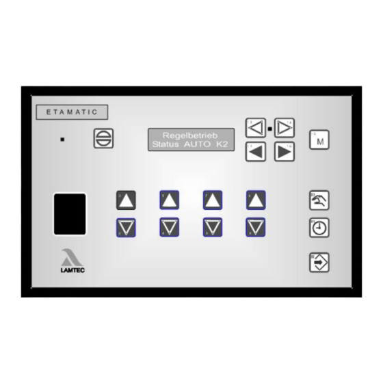
15 simultaneously to change to display "UEAN" Changing display – fuel/air ratio controll – – flame intensi- – power control Fig. 3-1 Front panel ETAMATIC Legend for mode of operation and options: PARM = Parameter settings AUTO = Automatic EINS Setting SPLO = Clear memory... -
Page 14: Operating Description
The ETAMATIC then interrogates the boiler safety interlock chain (ETAMATIC) or the common safety interlock chain (ETAMATIC) and the contact of the air pressure monitor. If it does not detect an "OK" condition, the text of a corresponding message appears and the operating con- trol stops. -
Page 15: Commissioning
Before Commissioning 5.1.1 Basic Settings First you must configure the device (ETAMATIC) for the requirements of the system. Therefore, you have to set the following parameters. We recommend to use the LAMTEC PC software for Windows (available separately). The factory standard settings are indicated by *. -
Page 16: Edit Parameter
Commissioning 5.1.4 Edit Parameter LED between key 13 and 14 shines (key is in function) set with keys 13 and 14 PARM at the display select with keys 6 and 7 the desired Parameter with keys 8 and 9 change the content in steps of 1 Digit. with keys 4 and 5 change the content in steps of 100 Digits. -
Page 17: Character Of The Output Channels
Commissioning 5.1.6 Character of the Output Channels Select parameter 356 - 359 (channel 1 to channel 4). Enter the type of control element which is connected. Short Text Description Default Fkt. K Function definition channel1 Category = channel configuration and broken wire detection In this parameter you define the type of actuator which controls the respective output channel. - Page 18 15/31 This parameter defines, which channel is active with which curve set. All channels are active by default (con- tent 31, in ETAMATIC 15). The following function may be realised. Example: changing channel activities with fuel oil/gas emergency operation with or without frequency con-...
-
Page 19: Start With Or Without Pilot Burner
Commissioning 5.1.7 Start with or without Pilot Burner Select parameter no. 774 and 775 (oil operation, gas operation). Short Text Description Default ZüBr. ÖL Start with (1) or without (0) pilot burner for oil, (2)=oil with continuous ignition flame 0 = start without pilot burner - oil operation 1 = start with pilot burner - oil operation 2 = pilot burner also active in burner operation with continuous monitoring of the ignition flame. - Page 20 Commissioning Short Text Description Default ZüBr.Gas Start with (1) or without (0) pilot burner for gas, (2)=gas with continuous ignition flame 0 = start without pilot burner - gas operation 1 = start with pilot burner - gas operation 2 = pilot burner also active in burner operation with continuous monitoring of the ignition flame.
-
Page 21: Pre-Purge Period
If the device is an ETAMATIC or a FMS, set the delay time in seconds before the recirculation flap opens, i. e. during this period only the boiler is ventilated. -
Page 22: Deactivate Firing Rate Control Unit
1, the integrated PT100 input is used, otherwise the firing rate input. If the ETAMATIC uses the PT100 input as the actual value signal for the internal firing rate controller, you may deactivate the firing rate controller with a bridge between terminals 19 and 20. -
Page 23: Minimum Running Time Of The Fuel/Air Ratio Control
Post-purge time (in seconds) 0 = no post-purge 1000 = continuous purge (from 5.0 on) Set the duration, how long the VMS/FMS/ETAMATIC purges after a switch OFF. The air flaps were open for this purpose. A fan output runs to 20mA. The FMS/ETA- MATIC holds the release signal of the fan. -
Page 24: Parameters Of The Interface
(19,200 baud). If the display shows problems with the serial transmission (especially with long serial connec- tions), it may be helpful to drop the baud rate. This must be carried out on the VMS/FMS/ETAMATIC as well as on the operating device e.g. laptop. 0 = 1200 Baud... -
Page 25: Deactivate Leakage Test
D.n.Abs Leak check after switching off (0-OFF / 1-ON) Select the leakage test after switch off (only FMS and ETAMATIC with integral leakage test) 0 = leakage test off after switch OFF 1 = leakage test on after switch OFF Activate the function of this parameter with the release of the leakage test (P 3). -
Page 26: Set Pilot Burner (Maintenance Mode)
Automatic restart after fault Automatic restart of the burner on fault condition. In the case of a fault for which the standards permit an auto- matic restart for FMS/ETAMATIC, this parameter initi- ates the restart. = no restart of the burner 1... -
Page 27: Burner Firing Rate Controller
Commissioning 5.1.19 Burner Firing Rate Controller 5.1.19.1 Enter Set Point Values Select parameter 796 and 798 (setpoint value 1 and setpoint value 2). With control by atmospheric condition select additionally parameter 797 and 799. Short Text Description Default Soll1min Controller setpoint 1 minimum Firing rate controller setpoint 1 minimum (setpoint 1) in °... -
Page 28: Control Range
Commissioning 5.1.19.2 Control Range Select parameter no. 802 and 803 Short Text Description Default EinschPt Burner start point Enter the switching point of the firing rate controller as the difference to the set point. [Switching point] = [setpoint] - [parameter content] e. -
Page 29: Setting The Control Thermostat
Commissioning 5.1.19.3 Setting the Control Thermostat Select parameter no. 804 Short Text Description Default Bren.AUS Burner off Burner off (difference to the set point) in ° C or bar (xx.x) Enter the firing rate controller switch off point. The entered value corresponds to the difference between the current set point and the value, which shuts down the burner. -
Page 30: Display Of The Units Of The Burner Firing Rate Controller Values
1 = display in °C (0... 320 °C) 2 = display in bar (P 810 and P 811) Select also for ETAMATIC, from which input the actual value signal should be taken. If the parame- ter is set to 1, the integrated PT100 input is used, otherwise the firing rate input is used. -
Page 31: Setting
Setting the Limit Switches of the Motors As soon as the ETAMATIC is supplied with voltage, it attempts to drive the actuator motors to the lower limit of the factory set curve. If the end-bearing's limit switches are not properly ad-... -
Page 32: Clear Memory
Commissioning 5.2.2.2 Clear Memory Press key 16 twice ("setpoint" display) Press key 14 twice the display shows SL in its centre. Press Enter key 11 “ENTER” the display shows "cleared", the old curve is cleared. 5.2.3 Programming the Ignition Point Press key 13 ... -
Page 33: Saving Curve
Commissioning 5.2.6 Saving Curve Press key 13 (switch unit from “ONE” to “Automatic” ) the display shows “Memory“ 5.2.7 Changing Points Points can be changed at any time by selecting the firing rate rating for the required point and re-entering the associated position of the control element. -
Page 34: Re-Enter Range Limits
Commissioning 5.2.9 Re-enter Range Limits If you change the limit switches after the programming, you must determine the range limits again. Enter password (see chapter ExternalLink: Passworteingabe). Press key 14 the display shows "SL" in its center Press key 11 ENTER the display shows "cleared". -
Page 35: Recalling Fault History
Press keys 3 and 2 to browse through the fault history. NOTICE If it is certain that the ETAMATIC has carried a voltage at all times since the last fault, it is pos- sible, that from the present output of the running time counter and the current time, to deter- mine at which time the fault occurred. -
Page 36: Calling The Checksums
Press key 11 ENTER. The following values are displayed one by one: CRC 16 of the levels 0, 1 and 2: adjustable at commissioning time 4: adjustable by LAMTEC only safety time oil in seconds safety time oil in seconds... -
Page 37: Trim
O setpoint value (below the second monitoring band) and corrective actions by the ETAMATIC cannot clear this error, then the trim is deactivated and the base value for air deficiency errors will be put out. -
Page 38: Calling Fault History O Trim
30 sec are stored. They are only stored in the EEPROM once the fault is cleared up or the ETAMATIC leaves the operating mode or control or base firing rate. Automatic Function Monitoring During Operation 6.5.1... -
Page 39: O 2 Monitoring Band
Trim 6.5.2 Monitoring Band During burner operation, the actual O value is continuously monitored for one maximum and two minimum permissible values. These ranges are located around the O setpoint as a func- tion of firing rate. If the actual values stay outside these bands for a defined period, the control system is deactivated and a “Fault”... -
Page 40: Dynamic Probe Test
Full firing rate (parameters 932 / 934) 70% 6.5.4 Dynamic Probe Test The ETAMATIC monitors the measured O value for changes during operation. If a fluctuation no higher than 0.2 O vol.% is detected over a period of 10 minutes, a state of excess air is enforced by changing the fuel/air mixture. -
Page 41: Control Strategy
-50% to +50%, the correction value (neutral value) output is 500; in the case of -30% to +70%, the output value is 300. NOTICE The neutral value corresponds to the base settings of the ETAMATIC without control. -
Page 42: Connecting The O 2 Measurement Device
Fig. 6-1 Connection to the O measuring device via LAMTEC SYSTEM BUS Connecting diagram see chapter ExternalLink: LAMTEC SYSTEM BUS. The LAMTEC SYSTEM BUS transmits the following signals to the ETAMATIC: • probe current • probe current during calibration •... -
Page 43: Operation And Display Of The O2 Trim
Trim Operation and Display of the O2 Trim Press key 15 once, to switch the display to O -trim. When you have switched to "Status", the display shows the O actual value and O setpoint value. The display shows the values in brackets, if O trim is deactivated. -
Page 44: Calling Up O 2 Trim Text Messages
Trim 6.8.2 Calling up O Trim Text Messages Switch display to O trim press key "RESET" press key M press key "ENTER" to call up the text messages press key "ENTER" again back Commissioning 6.9.1 Setting the Correction Range and the Correction Mode The correction value (control signal) transmitted to the electronic fuel/air ratio control is 0 …100% with a resolution of 0.1%. -
Page 45: Available Correction Modes
Trim 6.9.2 Available Correction Modes 6.9.2.1 CorrectionType1 Correction type 1 is used when correction is applied to a linear control element, e.g. to the fre- quency converter’s setpoint for adjusting the combustion air blower’s speed. The correction is directly added to or subtracted from the setpoint. Correction mode: Effect to the setpoint axis Fig. -
Page 46: Setting The Correction Range
Trim 6.9.2.2 Correction Type 2 Correction type 2 is used where the correction is applied to a non-linear control element, e.g. air damper. The curve's slope is taken into account before calculating the correction. A flatter curve results in a smaller correction range, whilst a steeper curve results in wider range. Correction mode: Effect to firing rate axis +60% to -40% Fig. -
Page 47: Calling Up The Set Correction Mode
Press key 11 "ENTER“ to confirm. Take the correction into account during later programming. The correction actuator must be able to operate without the ETAMATIC reaching the end-stop (0 or 999 or limit stop values). If the correction actuator cannot be driven all the way as required because a channel has reached the range limit determined during pre-purge, the burner's output is increased or de- creased until the actuator can be driven all the way. -
Page 48: O 2 Curve Input
Trim 6.9.6 Curve Input Press keys 13 and 14 to select "Set O ” Delete the entire O curve with Key 9 If only points should be modified, press key 8 Set to firing rate value with keys 16 and 17. Use keys 2 and 3 to start the programmed firing rate points of the common fuel/air ratio control curve. -
Page 49: Manual Calculating And Setting Of The Control Parameters
Trim 6.9.6.2 Manual Calculating and Setting of the Control Parameters Set firing rate controller to "Manual” and run to low firing-rate. Enter password (see chapter ExternalLink: Passworteingabe) press keys 13 and 14 to select "Set O " press key 8 to confirm the query press key 16 until the display shows "setpoint"... - Page 50 Trim If a fault occurs in the O trim will be deactivated, and depending on the cause the preset cor- rection value for "Deactivated O control” or "Air deficiency” would be shown as output. The burner does not shut down. In the event of an "Air deficiency fault”...
- Page 51 Trim Short Text Description Default O2Stoer Safety shut-down by O /CO controller allowed? (0- never, 1-when insufficient air) In case of a fault of the O trim, the O trim will be deac- tivated. Depending on the cause, the defined correction value for "deactivated O trim"...
- Page 52 Trim Short Text Description Default O2NeutrB Correction value output when O trim is deactivated. 1000 Correction value is displayed at deactivated O trim. Fuel 1 (from 5.0 on): at P 7 = dec 32 and P 847 = 2, 3 or 4: CO/O controller slave / correction 1 via LSB 0 = the last received value is permanent valid...
-
Page 53: Internal Burner Firing Rate Controller
Actual value (temperaturePT 100 max 320 °C or steam pressure) • Outside temperature or another analog signal for setpoint shift (only on control by atmos- pheric condition). The ETAMATIC must be equipped with the optional hardware for control by atmospheric condition. •... -
Page 54: Enter Setpoint Of Firing Rate Controller
0...5 k resistance signal, terminal 4, 5 and 6 • directly as PT 100 terminal 21, 20, 19 as three-wire connection (0 – 320 °C) Outside temperature (setpoint-shifting) - only available if ETAMATIC has the option "control by atmospheric condition" •... -
Page 55: Operating Description
Internal Burner Firing Rate Controller Operating Description The burner start-up is carried out as described above. At least ’Burner ON’ signal and ’Re- lease’ must be sent by firing rate controller. The burner starts as soon as it is receiving signals ’Burner ON’ and ’Release’ from firing rate controller. -
Page 56: Setpoint Changeover
Internal Burner Firing Rate Controller 7.10 Setpoint Changeover You can switch the setpoint with the input "setpoint switchover". If you use a version with fixed setpoint value it is possible to select one of the two values, which are entered in the parame- ters 796 and 798 with this contact. -
Page 57: Start-Up Sequence
Internal Burner Firing Rate Controller 7.11 Start-up Sequence The firing rate controller has a startup circuit, in order to slow down the burner's start firing rate. The startup circuit is run during each new burner start. The internal firing rate is held at a value P 792 adjustable by the user, for as long as the boiler is cold (actual value is below a user- adjustable limit, P 791). -
Page 58: Thermostat And Control Range
Internal Burner Firing Rate Controller 7.12 Thermostat and Control Range The thermostat function switches the burner on and off on the basis of the temperature and/ or pressure value, but only when burner is released by the start signal. The control range is formed by entering the controller setpoint value and the parameters P 802 (switch-on point), P803 (upper control range) and P 804 (burner OFF). - Page 59 Internal Burner Firing Rate Controller Short Text Description Default EinschPt Burner start point Enter the switching point of the firing rate controller as the difference to the set point. [Switching point] = [setpoint] - [parameter content] e. g. : burner should switch on at 110. setpoint = 120, parameter content = 10, 110 = 120 - 10 If the burner shall start above the setpoint,...
-
Page 60: Manual Control
"Manual" again You also may switch the ETAMATIC to "Manual Control" with the terminals. By short-circuiting the PT 100 signal (e.g. bridge terminal 19 and 20) the burner firing rate controller is switched off. -
Page 61: Control Range
Internal Burner Firing Rate Controller 7.16 Control Range The control range lies around the setpoint. The content of the "Burner on" parameter is sub- tracted from the setpoint value to form the switch-on value. The value of the "Upper control range"... -
Page 62: Control Mode
Control Mode Control Mode The firing rate controller tries to bring the actual value into line with the setpoint value. In doing so, a direct correlation is assumed between internal firing- ate and boiler temperature, e.g. the greater the internal firing rate, the faster the boiler temperature rises. Should the curves be programmed differently, the firing rate controller will not function. -
Page 63: Aides For Setting
Control Mode Aides for Setting Characteristic Control Process Control Mode Start-up Procedure P term higher decrease of stronger reaction with faster start-up with attenuation overshoot overshoot P term smaller increase of less reaction, less ten- slower startup attenuation dency to oscillate Fig. - Page 64 (gas pressure > min. = 0). The ETAMATIC checks this. Main gas 1 is then opened shortly and gas flows into the test line (gas pressure > min. changes from 0 to 1). This pres- sure must then subsist for 30 seconds.
-
Page 65: Valve Leakage Test
Control Mode 8.2.1 Valve Leakage Test Flow Chart Fig. 8-4 Valve leakage test flow chart... -
Page 66: Valve Leakage Test Flow Chart
Control Mode 8.2.2 Calculation Example An (approximate) formula for calculating the valve leakage test monitoring facility is summa- rised below: Definitions: GDW: gas pressure monitor gas-side safety shut-off device burner-side safety shut-off device barometric air pressure < 1000 mbar lower GDW switching point (falling) upper GDW switching point (rising) p = P GDW switching difference... -
Page 67: Calculation Of Gas Pressure Switching Point > Min
Control Mode 8.2.2.1 Calculation of Gas Pressure Switching Point > Min Example of calculation: with Values: (barometric air pressure) (volume of the revised gas route) (test time) (gas flow pressure, pre-pressure before V1) (maximum gas flow rate) are 0,1 % of Q = 2200 m Calculation: Lower switching point:... -
Page 68: En13611:2012)
Control Mode 8.2.2.2 Calculation of Gas Pressure Switching Point > Min (according to EN13611:2012) Example of calculation: Values: (volume of the revised gas route) (gas flow pressure, pre-pressure before V1) (maximum gas flow rate) sind 0,1 % von Q = 2200 m Calculation: Upper switching point: Lower switching point:... -
Page 69: Standby
8.2.3 Standby 8.2.3.1 Standby mode In this mode the ETAMATIC enables a switchback to pilot burner mode. The burner re-starts without pre-purge in the 2 safety time. You can activate STANDBY mode, if the internal firing rate controller is active or if an external input or output command can be connected to LSB module or fieldbus (see parameter 812, access level 4). - Page 70 Control Mode As soon as one of the following incidences happen, the parameter set ignition sequence of the fuel is executed without switching on the ignition transformer: – Boiler pressure or boiler temperature have lapsed to that point, where the burner would start again (with internal firing rate controller) –...
-
Page 71: Switching Into Standby Mode Via Lsb Module
Control Mode 8.2.3.2 Switching into Standby Mode via LSB module Fig. 8-7 Switching in STANDBY mode via LSB module... -
Page 72: Appendix
Appendix Appendix Mode Abbreviations Used Fig. 9-1 Status display at customer interface Short text Description → READY (signal on terminal 58) ZÜ → IGNITION POSITION or IGNITION → SETTING/IGNITION position (same as IGNITION, but Gerät on SET- TING) → BASE FIRING RATE →... -
Page 73: Flame Monitoring
The F250 flame scanner as well as FFS05 and FFS06 flame sensors are discontinued since 01/2014 and are not taken into account in the current certifications. Approvals for flame scanner/sensor in conjunction with ETAMATIC with validity from that date are not valid for F250, FFS05 or FFS06. -
Page 74: Self Monitoring
Appendix 9.2.1.3 Self Monitoring – Signal processing with two separately constructed and alternately activated transmission channels. – Continuous comparison of the output levels for anticoincidence. The transmission range of the digital frequency analysis covers signal transmittance between 10Hz or 25Hz (factory configuration) and 200 Hz. Mains frequency signals and their harmonics are filtered, with a filter bandwidth of 3 Hz. -
Page 75: General Information Of The Optical Flame Monitoring
IP 65. The computing circuit for all sensor types is located in the ETAMATIC. Cabling from the sensor to the ETAMATIC is 5-pole, static-screened with the sensor housing's potential (operating earth connection), a six cable is for measuring the flame signal during... -
Page 76: Avoiding Emc Effects
Appendix WARNING! If the ETAMATIC is used with an integral flame monitor, terminal 53 may not be connected to any other components The optical flame sensors are supplied together with a connecting cable of ca. 2 m length. The line between the sensor and the flame monitoring unit may be extended up to a distance of 500 m. -
Page 77: Fault Codes
The flame signal extinguishes during the first safety time H/Ü Check flame stability. Check set pilot burner. Check flame sensor. ETAMATIC: Check Jumper. The flame signal extinguishes during the second safety time H/Ü Check flame stability. Check wiring. Check flame sensor. - Page 78 Appendix Fault Restart according to Description Code EN676 Flame signal does not appear during safety time H/Ü Check flame stability. Check wiring. Check flame sensor. Check Parameter 774, 775 and 788. Flame signal goes out immediately after ignition H/Ü If the flame extinguishes within three seconds after ignition, fault H010 is shown; after that, fault H004 appears.
- Page 79 Appendix Fault Restart according to Description Code EN676 Internal fault: Error in misc. data H/Ü The fault can occur during an internal self-test. A fault was discovered during the reading of the redundant data in the EEPROM. Reset the fault. In the process, switch the mains voltage off and on again if neces- sary.
- Page 80 For more details, see the "Protected data record" description in the remote control software. If this is not possible, you must order a preprogrammed EEPROM from LAMTEC. When ordering, you must enter the device number and software checksums. Only in this way are mix-ups excluded. For the address, see the overleaf of this publica- tion.
- Page 81 If fault messages are constantly appearing one after the other the EPROM pro- gramme is possibly defective. Request a new programme EPROM from LAMTEC with the precise specification of the respective purchase order number, sales order number, and commission of the device.
- Page 82 Appendix Fault Restart according to Description Code EN676 RAM-Test detected error H/Ü Fault during an internal self-test. Reset the fault; switch the mains voltage off and on again if necessary. Check all fuses in the device. Check the curve points of the main and monitoring processors for irregularities. ...
- Page 83 For more details, see the "Protected data record" description in the remote control software. If this is not possible, you must order a preprogrammed EEPROM from LAMTEC. When ordering, you must enter the device number and software checksums. Only in this way are mix-ups excluded. For the address, see the overleaf of this publica-...
- Page 84 Appendix Fault Restart according to Description Code EN676 Potentiometer faulty, feedback changing too quickly: channel 1 H/Ü The return values of a three-point-step servo output change faster than specified as maximum in parameters 12-16. Check the wiring; check the potentiometers for short circuit. It is possible that the range limit switch is set higher than the end of the range of the potentiometer.
- Page 85 Appendix Fault Restart according to Description Code EN676 >88 the same as P 151, but channel: 5 H/Ü See S151 >88 Monitoring direction of ratation: channel 1 H/Ü The channel is not running or does not start on time. During operation, the channel briefly changes direction.
- Page 86 Appendix Fault Restart according to Description Code EN676 1st monitoring band over range too long. Channel: 2 H/Ü 1st monitoring band over range too long. Channel: 3 H/Ü 1st monitoring band over range too long. Channel: 4 H/Ü 1st monitoring band over range too long. Channel: 5 H/Ü...
- Page 87 Appendix Fault Restart according to Description Code EN676 >88 Fuel/air ratio control blocked: channel 3 >88 Fuel/air ratio control blocked: channel 4 >88 Fuel/air ratio control blocked: channel 5 Broken wire at firing rate input -1 H/Ü Check the wiring. Broken wire at firing rate input-2 H/Ü...
- Page 88 Appendix Fault Restart according to Description Code EN676 permissible O value was fallen below Initially, the time from parameter P904 "O trim active after ignition in seconds" runs out before the fault is permitted. After that, the monitoring time from P966 starts. Also works without an active O controller (from 5.4):...
- Page 89 Check all fuses in the device. If fault messages are constantly appearing one after the other <Symbol For- mat="Symbol">→ </Symbol> exchange the device or respective card. Internal comparison: The relay output terminal 43 or 68 (ETAMATIC) does not respond. See S500 Internal comparison: relay out terminal 16 or 65 (ETAMATIC) not picking up.
- Page 90 Description Code EN676 Internal comparison: relay output terminal 67 not dropping out. See S500 Internal comparison: relay output terminal 43 or 68 (ETAMATIC) not dropping out. See S500 Internal comparison: relay output terminal 16 or 65 (ETAMATIC) not dropping out.
- Page 91 Appendix Fault Restart according to Description Code EN676 TRIAC selftest : oil valve is currentless See S500 TRIAC selftest : Ignition transformer is currentless See S500 TRIAC selftest : ignition valve is currentless See S500 Oil fuel blocked because a required solenoid valve is not connected The test current for the TRIAC self-test cannot flow.
- Page 92 Appendix Fault Restart according to Description Code EN676 Ignition flame goes out in standby operation Continuous ignition flame goes out under operation Oil circulation: Temperature does not rise up within 45 sec. Oil lance blow out: Delay for opening not kept Oil lance blow out: Oil valve actuator not in ignition position Oil lance blow out: blow out period too long Atomizer switch-ON-pre-period not kept...
- Page 93 Appendix Fault Restart according to Description Code EN676 Gas valves open when burning oil Ü Oil valves open when burning gas Ü Main gas 2 open without main gas 1 Ü Main gas 1 illegally open Ü Main gas valves and ignition valve open too long Ü...
- Page 94 Appendix Fault Restart according to Description Code EN676 Programme check time exceeded. Ü Solenoid value switch-off faulty Ü Leak check: ventilating into boiler not allowed Ü Shut-down on faults via bus. Ü >88 No data transfer via the bus (time-out). Ü...
- Page 95 Remote-fault-reset happens within a too short distance EN 14459 permits a remote unlocking only 4 x within 15 minutes. The fault release is monitored by the remote control software, LAMTEC system bus, and field bus (parameter 19). When exceeded, fault deactivation H889 is gen- erated and additional remote fault releases are ignored.
- Page 96 Check all fuses in the device. If fault messages are constantly appearing one after the other exchange the device or respective card. Curve set adjustment via LAMTEC SYSTEM BUS, selftest recognizes fault Error in reference, channel: 1 Ü Fault during an internal self-test.
- Page 97 Restart according to Description Code EN676 Relay driver self-test : output terminal 11 or 66 (ETAMATIC) faulty. H/Ü Fault during an internal self-test. Reset the fault; switch the mains voltage off and on again if necessary. Check all fuses in the device.
- Page 98 ETAMATIC: Before A4a4002: the "Air pressure monitor" input appears during the TRIAC self- test before the fan output is actuated by ETAMATIC! Internal fault number 7: This fault occurs when the "Burner On" and "Pre-venting" signals occur in the wrong order or too quickly in sequence during the postpurge time in the case of devices without a burner sequencer (VMS / ETAMATIC V).
-
Page 99: Calling Up The Condition Of The Digital Inputs
Appendix Calling Up the Condition of the Digital Inputs press keys 16 and 17 to switch to the digital inputs Significance of ETAMATIC digital input display signal is active signal is inactive only with ETAMATIC without front panel... -
Page 100: Tips And Tricks
If it is required to measure the installation's safety times at a later time (e.g. as part of an in- stallation's acceptance tests), it is not sufficient to disconnect the magnetic valves before start- up. This is recognised by the ETAMATIC's self-testing circuit, and results in emergency shut- down. -
Page 101: Process Sequence Charts
Appendix Process Sequence Charts Fig. 9-4 Process sequence chart: gas with pilot burner... - Page 102 Appendix Fig. 9-5 process sequence chart gas without pilot burner...
- Page 103 Appendix Fig. 9-6 Process sequence chart oil with pilot burner...
- Page 104 Appendix Fig. 9-7 Process sequence chart: oil without pilot burner...
- Page 105 Appendix Key to process sequence charts Any condition Wait for gas safety interlock circuit air pressure monitor min. scan Time for pressure build-up in the gas test line (only with valve leakage test activated) 2 sec. Servo drive running time 30-60 sec.
- Page 106 (chargeable option) The ETAMATIC S has no monitor output, because the setpoint of channel 1 is preset by terminals 1 and 2. The output (e.g. internal firing rate) is adjusted via optional LSB module’s.
- Page 107 (P 18 = 1) WARNING! P 762 = 0 terminal 46 has no function (ETAMATIC OEM and Burner Control FA1! P 17 = 3 (FA1 special) terminal 46 is set to "ignition position acknowledgement! "Oil pressure > min" / "atomiser air pressure" is not monitored via terminal 46!
- Page 108 (2 safety time) and ends after the duration, set in this parameter has passed. ETAMATIC OEM This parameter effects the safety interlock chain oil as well as the oil pressure min. Fkt <max Function mode of gas pressure < max. switch ETAMATIC input terminal 54 0 = recirculation "ON"...
-
Page 109: Connection Diagrams
Appendix Connection Diagrams... - Page 110 Appendix Fig. 9-8 ETAMATIC wiring diagram with ignition flame monitoring (footnotes see pages before) Fig. 9-9 ETAMATIC S wiring diagram with ignition flame monitoring...
-
Page 111: Connection Examples Regular Firing Rate Input
Appendix Connection Examples Regular Firing Rate Input Connection examples firing rate default Where current is used as firing rate default signal instead of a potentiometer: f.ex. active steam pressure controller Where a three-point step signal from the firing rate controller is used as firing rate input, you must connect the contacts instead of the potentiometer of the firing rate: Where a 4-20mA unit shall be supplied with 24V (e.g. -
Page 112: Connections In Non Grounded Power Line Networks
If you use a Gerät in a non-grounded power line network, you have to connect the Gerät up- strem to a mains filter. Description mains filter type 663 R 4050 ETAMATIC PE bar 9.11 Fan Force-Open during Fault Fig. 9-10 Connection of a frequency inverter... -
Page 113: Connection Flame Scanner
9.12 Connection Flame Scanner Fig. 9-11 Connection flame scanner Fig. 9-12 Connection flame sensor FFS07/FFS08 Flame intensity to align the flame sensor (not connected during operation) with delivery of 01.01.2003 on. Abbreviation Description Abbreviation Description ETAMATIC Black White Pink Green... - Page 114 Appendix Abbreviation Description Abbreviation Description Blue Yellow PE-bar NOTICE Optional connection to FPE schield for drainage from extraordinary EMV faults. The connec- tion leads to a short circuit between device ground and FPE. This can be of influence to the devices with the same ground reference.
-
Page 115: Lamtec System Bus (Lsb)
Configuration of the Processor Board NOTICE The LAMTEC SYSTEM BUS may not be connected with a branch cable and has to be termi- nated at both sides with 120 Ω. Fig. 9-13 Configuration of the processor board LT1/LT2 to LAMTEC SYSTEM BUS (LSB) 9.13.2... - Page 116 Appendix Fig. 9-15 LSB connection ETAMATIC - LT2 - other LAMTEC devices Description To other LAMTEC-devices Housing Pre-canned line 2 m PE-bar in housing LT2 Terminal resistance passive Fig. 9-16 LSB connection ETAMATIC o LT1 from SN 600 on Description...
- Page 117 Appendix Fig. 9-17 LSB-Connection ETAMATIC - LT 1 to SN 0599 Description PE-Track in system-cover LT1 Cover Pre-canned line 2 m, 663R0421N LT1 from serial number 0599 Terminator enable Fig. 9-18 LSB Connection ETAMATIC - LT3-F Description LSB connection plug, termination resistor 120 , ON...
-
Page 118: Lamtec System Bus Plug
With a slide-switch you can set the termination of the LSB. If You place the device at the beginning or the end of the LAMTEC SYSTEM BUS, you must set the slide of the plug to ON (terminator active).If you place the device at another position of the LAMTEC SYSTEM BUS, set the slide to OFF (terminator inactive). - Page 119 Fig. 9-20 Pin assignment LSB plug Description 9 pole Sub-D jack service- and programming interface for the operating unit Switch for activating/deactivating the LSB-termination ON.-.OFF 9 pole Sub-D pikes LSB for connection with the ETAMATIC Clamp-connection Solder pins Shielding...
-
Page 120: Modem For Remote Control
A connection with Gerät via modem is also possible. The indus- trial modem (optional) for mounting on top hat rail allows the access to 31 devices at the same time with a LAMTEC tool for Windows. This tool realizes the remote control of the operating... -
Page 121: Inernal Connecting Diagram Of The Control Output Device
Fig. 9-23 Internal connecting diagram of the control outputs Always connect the attached firing rates (valves etc.) to the ETAMATIC (even when the burner is off). If You could not ensure this, use an RC combination (ca. 0,15μF, ca. 220 ) between the output terminal and neutral to let the testing current flow. -
Page 122: Valve Leakage Test Venting Over The Roof
Ensure that this time is long enough, even for mostly used gaspipes with a smaller diameter to release the gas. Fig. 9-25 Suggested wiring for venting the gas line over the roof in conjunction with the ETAMATIC An ETAMATIC is controlling 2 burners in parallel. - Page 123 Appendix Fig. 9-26 2 Gas pressure monitor at ETAMATIC Valve leakage test after shut-down is not possible. Description Main gas 1 Gas pressure >min Gas pressure >min...
-
Page 124: Switch- And Key Combinations
11 (Enter) key no value feed- back Call up flame intensity Automatic press key 15 / F4 (M) twice Without integral flame monitoring, the dis- play shows "---%" Mode switching with O trim Automatic press key 15 (M) twice ETAMATIC... -
Page 125: Sensor
Appendix Action Display Mode Buttons / Other mode O trim Status trim Mode O trim, press key 11 (Enter) to acknowledge Calling up text messages Status trim press key 11 (Enter) Display monitoring mode Automatic hold and press 13 Setting Change in mode T firing rate key 11 (Enter), Key 5... - Page 126 Direct connection of Speed sensor (actual version) In ETAMATIC S, a r.p.m board can be integrated, allowing you to connect an inductive sensor for speed feedback directly. It could be a NAMUR type or a three wired type. The selection of the type and the range is only factory setting.
- Page 127 Fig. 9-30 Basic board ETAMATIC S Description Plug-in position r.p.m. board on basic board ETAMATIC S R.p.m. board 663P8012 built in basic board If the set pulse range is exceeded the value remains at the upper end of the range (higher pulse numbers are ignored).
-
Page 128: Selection Of A Suitable R. P. M. Sensor
Owing to the large number of usable transducers LAMTEC has only one two wire element and one three wire element in it’s product range. It is selected in that way, that it covers a number of measuring tasks. Other transducers only on enquiry or direct from the company Turck. - Page 129 Appendix 1 = r.p.m. sensor Fig. 9-33 Position r.p.m. sensor to the attenuating element Fig. 9-34 Dimensional drawing attenuating element for our exam- The illustration (left) shows a typical arrangement of attenuating element, sensor and shaft. How the system works: Every inductive sensor forms an electric field at its active surface, from which the contact gap (nominal contact gap "Sn”) can be derived as a function of sensor size.
-
Page 130: Circuit Proposal 3-Wired Speed Sensor With Higher Power Supplay Voltage
Power supply: 24 V Pulse voltage: ca. 11 V ETAMATIC S is provided with a 3-wired pick up sensor with approx. 13 V voltage. This is suf- ficient for Turck Bi4-M12-AP6X as it is tested and approved by LAMTEC. For pick up sensor which requires a higher power supply voltage (e.g. -
Page 131: External Switching Of The Fuel Motors/ Valves
Appendix 9.19 External Switching of the Fuel Motors/ Valves If there are not enough output channels, it is possible to switch externally between actuators, which are not needed in every curve set (oil motors and gas motors). WARNING! If you use an external switching you must recognise this for safety reasons: You must ensure that the feedback of the selected motor is also selected, e.g. - Page 132 Appendix Description Fuel selection Fuel selection Safety interlock chain oil Safety interlock chain gas L 230VAC, delay fuse provided Open Close Control drive oil Control drive gas...
-
Page 133: Feedback At Three-Point-Step Channels
Feedback at Three-Point-Step Channels 9.20.1 Connect with Positive Locking Since the ETAMATIC, in the case of three-point step channels, adjusts the damper until the actual value is equal to the setpoint value, the feedback potentiometer must always reliably correspond to the damper position. - Page 134 Rating Contelec PL 295 Rating: 5 kΩ* Bourns 6639S-095-.. Rating: 5 kΩ* Other potentiometers are permitted only after consulting LAMTEC or the TÜV. Examples of servomotors Servomotors with approved potentiometer, fitted with a positive interlock connection: Manufacturer Description Potentiometer LAMTEC 662R2111...
-
Page 135: Changing Control Drives / Potentiometers
This may lead to an other position of the damper. WARNING! Therefore you must prove the burner adjustment again in all firing rate positions and all oper- ation modes. If necessary adapt the curves in the ETAMATIC. 9.21.2 How to Replace a Potentiometer WARNING! Keep switches in the same position. - Page 136 Replace the electronic boards in the housing. Connect the PE-wire from the cover. Attach and screw on the side cover Replace ETAMATIC in the control cabinet and connect it again. Restore dataset! Before continuing, restore the protected dataset. 8. Commissioning: After you have replaced the old EPROMs and switched on the controller, the fault mes- sage “U106"...
-
Page 137: Wiring Notes
Individual optimisation provided by customer. 9.23 Wiring Notes 9.23.1 Shields Connection All cables from and to the ETAMATIC must be shielded (with the exception of the 230 V cable). Connect the shielding to PE by the shortest possible route. Right: shielding terminal connection terminal... -
Page 138: Control Cabinet Wiring
9.23.3 Control Cabinet Wiring The low-voltage cables from and to the ETAMATIC should not run in parallel to the power elec- tronics' in and out conductors in one cable duct. Frequency converter cables and switches/contacts carrying high inductive or capacitive firing rates are particularly critical. -
Page 139: Tolerance Limit In Direction Air Deficiency
Appendix press key 12 press keys 2 and 3 to run to the firing rate point for checking it wait until the system has run to that point enter password press key 14 one time (setting) – Adjust setpoint value of the three-point step channel in the air deficiency direction (for dead band setting, see parameters) –... - Page 140 Appendix With the aid of a protocol, it is possible to document that a check on the switch off limits is not necessary due to the relevant parameter settings. The setting values should be listed in the tables. The numbers are describing the parameter numbers or numbers, on which the settings are based of.
-
Page 141: Example Of A Protocol Of The Parameter Settings Of The Monitoring Bands
Appendix 9.25.1 Example of a Protocol of the Parameter Settings of the Monitoring Bands Date: Serial No.: Installation: Operating mode: Tolerance on air shortage side: Channel Functions Dead band Monitoring Band Band shift 32 /34 62 / 67 Channel 1 33 / 43 63 / 73 Channel 2... -
Page 142: Technical Data
The parasitic capacitance of the lead connected to the digital inputs may not exceed 2.2μF as Inputs a result of the ETAMATIC self-tests. The lead length should be limited to 100 m. Since the dig- ital inputs are for 24V DC, suitable contacts for that voltage should be used (hard silver or gold-... - Page 143 Appendix You may only use other servomotors with the permission of LAMTEC. Current consumption max 50 mA continuous current/starting current. Continuous control Apparent ohmic resistance: 4...20mA < 600 output Apparent ohmic resistance: 100 Analogue inputs ETAMATIC with Connectable flame sensors:...
- Page 144 State Input Number of program unlimited cycles Interfaces – 1 serial interface on 25-pole Sub-D-connector, addressable via LAMTEC adapter only (Dongle 663P0600)(RS 232) – 1 interface on 9-pole Sub-D-connector WARNING! Using the interface without the adapter may damage the device.
-
Page 145: Etamatic Without Internal Flame Monitoring
Appendix 9.27 ETAMATIC without internal flame monitoring Connectable flame detectors: Any tested flame sensor with error-proof floating contact for flame signalling WARNING! If a flame monitor, which is not approved for continuous operation is connected, the entire sys- tem's approval for continuous operation will loose it’s validation. -
Page 146: Dimensions And Weight
Appendix 9.28 Dimensions and Weight Dimensions ETAMATIC (l x w x d) 144 x 240 x 142 Installation depth 125 mm Weight 2,3 kg Protection class to DIN 10 050 IP 40 Installation ETAMATIC Panel mounting Position of use Fig. 9-38 Minimum distances in the case of several cut-outs Fig. - Page 147 F3 main gas 1 F4 main gas 2 F5 ignition transformer, fan, ignition valves, oil pump, fault S1 9-pole Sub-D connector for LAMTEC SYSTEM BUS S2 communications interface PC connection is possible only with LAMTEC interface adapter! Fig. 9-41 Rear view...
- Page 148 Appendix Fig. 9-43 Flame sensor FFS05, FFS07 (replaced by FFS05, connecting cable FFS07 includes 1 rs cord extra) Description type plate grounding M4 (Pozidriv 2) incidence of light bend radius of the FM wire min. 25 mm Fig. 9-44 Dimensional drawing FS60 for flame Fig.
- Page 149 LAMTEC Meß- and Regeltechnik für Feuerungen GmbH & Co. KG ................Address: Wiesenstraße 6, D-69190 Walldorf ................Product: ETAMATIC / ETAMATIC S ................Type approval: CE 0085 AU 0207 ................The indicated product complies with the regulations of following European directives: Number...
-
Page 150: Declaration Of Conformity
EC Declaration of Conformity or EC Manufacturer’s Declaration Month/Year: ........April../...2010......Product type: ETAMATIC / ETAMATIC S ............................................... Conformance of the product with the previously mentioned directives is given according to the following standards: Harmonised European Standards:... - Page 151 Appendix...
- Page 152 The information in this publication is subject to technical changes. LAMTEC Meß- und Regeltechnik für Feuerungen GmbH & Co. KG Wiesenstraße 6 D-69190 Walldorf Telefon: +49 (0) 6227 6052-0 info@lamtec.de Telefax: +49 (0) 6227 6052-57 www.lamtec.de Printed in Germany | Copyright 2016...
Need help?
Do you have a question about the ETAMATIC and is the answer not in the manual?
Questions and answers