Lamtec ETAMATIC Manual
Sensors and systems for combustion engineering
Hide thumbs
Also See for ETAMATIC:
- Manual (152 pages) ,
- Quick reference (62 pages) ,
- Quick reference (62 pages)

Related Manuals for Lamtec ETAMATIC


Summary of Contents for Lamtec ETAMATIC
- Page 1 Manual ETAMATIC / ETAMATIC S CE-0085 AU 0207 Sensors and Systems for Combustion Engineering...
-
Page 3: Table Of Contents
Table of Contents Table of Contents GENERAL INFORMATION ........7 Validity of these instructions. - Page 4 Table of Contents 5.2.7 Changing Points ............34 5.2.8 Saving Changes .
- Page 5 Table of Contents Brief Description ............52 Limit Ranges .
- Page 6 ETAMATIC without internal flame monitoring ........127...
- Page 7 Table of Contents 9.27 Dimensions and weight ........... . 128 9.28 Declaration of Conformity .
-
Page 8: General Information
General Information General Information Validity of these instructions These instructions apply to the ETAMATIC and ETAMATIC S in any configuration. This devices conform to the following standards and regulations: EN 230 EN 267 (where applicable) EN 298 EN 676 (where applicable) EN 746-2 (where applicable) EN 12952 -8 u.11 (where applicable) -
Page 9: Variants - Device Configuration
The variant number describes the device's variant. You will find the variant number on the side of the housing. The variant number is based on the following key: Serial number Example: ETAMATIC in variante no.: 0 0 001 r0 AM S AP ETAMATIC a: Flame monitoring ... - Page 10 2x DPS and 2x continuous output 4...20mA, FB C1 RPM-3L, 300-3600 I/min 31D 2x DPS and 2x continuous output 4...20mA, FB C1 RPM-3L, 300-3600 I/min d: O2/ CO control controller via LAMTEC SYSTEM BUS controller via external system /CO controller ...
-
Page 11: Safety
LAMTEC GmbH & Co KG will not be liable for damage or injury arising out of a failure to ob- serve the instructions above. The warranty and liability provisions of the terms and conditions of sale and supply of LAMTEC GmbH &... -
Page 12: For Your Safety
Safety For Your Safety In this operating instructions, the following symbols are used as important safety instructions to the user. These symbols appear wherever there is a need for this information in a particular section. It is essential to note and comply with the safety instructions, particularly the warnings. DANGER! Indicates possible danger to personnel, particularly with regard to electrical equipment WARNING! -
Page 13: Associated Automatic Flame Guard
LAMTEC GmbH & Co KG will not be liable for damage or injury arising out of a failure to ob- serve the instructions above. The warranty and liability provisions contained in LAMTEC GmbH &... -
Page 14: Brief Description
Brief Description Brief Description The ETAMATIC regulates up to 4 control elements as a function of a control variable, in ac- cordance with freely programmable curves. The ETAMATIC has 4 three-point step control out- puts. The ETAMATIC S has 3 three-point step control outputs and one 4-20 mA output. -
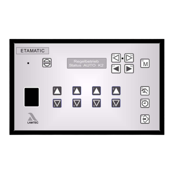
Page 15: Display And Operational Controls
digital inputs feedback Changing dis- play – compound – – flame tensity UEAN = Display of monitoring processor PARA = Parameterisation AUTO = Automatic EINS SPLO = Clear memory only if activated in the parameter section only in ETAMATIC S... -
Page 16: Operating Description
The ETAMATIC then interrogates the boiler safety interlock circuit or the common safety inter- lock chain (ETAMATIC) and the contact of the air pressure monitor. If it does not detect an "OK" condition, the text of a corresponding message appears and the operating control stops. -
Page 17: Commissioning
Before Commissioning 5.1.1 Basic Settings First you must configure the device (ETAMATIC) for the requirements of the system. Therefore, you have to set some parameters. The factory standard settings are indicated by *. We recommend to use the LAMTEC PC software for Windows (available separately). -
Page 18: Character Of The Output Channels
Commissioning 5.1.4 Character of the Output Channels Select parameter 356 - 359 (channel 1 to channel 4). Enter the type of control element which is connected. FMS ETA Short Text Description Default Fkt. K Function definition channel1 Category = channel configuration and broken wire detection In this parameter you define the type of actuator the respective output channel controls. - Page 19 15/31 This parameter defines, which channel is active with which curve set. All channels are active by default (con- tent 31, for ETAMATIC 15). The following function may be realised. Example: changing channel activities with fuel oil/gas emergency operation with or without frequency con- verter...
-
Page 20: Start With Or Without Pilot Burner
Commissioning 5.1.5 Start with or without pilot burner Select parameter no. 774 and 775 (oil operation, gas operation). FMS ETA Short Text Description Default ZüBr. ÖL Start with (1) or without (0) pilot burner for oil, (2)=oil with continuous ignition flame 0 = start without pilot burner - oil operation... - Page 21 Commissioning FMS ETA Short Text Description Default ZüBr.Gas Start with (1) or without (0) pilot burner for gas, (2)=gas with continuous ignition flame 0 = start without pilot burner - gas operation 1 = start with pilot burner - gas operation 2 = pilot burner also active in burner operation with ...
-
Page 22: Pre-Ventilation Period
Set in this parameter the number of digits the air channel has to reach, before recirculation becomes active. If the device is an ETAMATIC or a FMS, set the delay time in seconds before the recirculation flap opens, i. e. during this period only the boiler is ventilated. -
Page 23: Deactivate Load Control Unit
1, the integrated PT100 input is used, otherwise the firing rate input. If the ETAMATIC uses the PT100 input as the actual value signal for the internal firing rate controller, you may deactivate the firing rate controller with a bridge between terminals 19 and 20. -
Page 24: Post-Ventilation Time
OFF. The air flaps were open for this purpose. A fan output runs to 20mA. The FMS/ ETAMATIC holds the release signal of the fan. No post ventilation occurs if the parameter content is 0 and in the case of a fault shutdown. -
Page 25: Delaytime Of The Air Dampers During Pre-Ventilation
Enter a delay time for opening of the flaps with respect to the ventilator release. This prevents from increasing the power consumption of the ventilator motor in the star/delta starting phase (only effective for FMS and ETAMATIC). (from 5.4 / 52201 on) This parameter affects even with continuous ventilation. -
Page 26: Parameters Of The Interface
(19,200 baud). If the display shows problems with the serial transmission (especially with long serial connec- tions), it may be helpful to drop the baud rate. This must be carried out on the VMS/FMS/ETAMATIC as well as on the operating device e.g. laptop. ... -
Page 27: Set Pilot Burner (Maintenance Mode)
Commissioning 5.1.15 Set pilot burner (maintenance mode) Select parameter no. 787 FMS ETA Short Text Description Default Wartung Maintenance mode (control unit only until stabilization time) 0 = maintenance mode on (main valves are opened) 1 = maintenance mode active 2 = curve set switch allowed in set mode Set the maintenance mode with this parameter. -
Page 28: Automatic Restart After Failure
Automatic restart of the burner on fault condition. In the case of a fault for which the standards permit an auto- matic restart for FMS/ETAMATIC, this parameter initi- ates the restart. Set to 0 for VMS. 0 = no restart of the burner... -
Page 29: Burner Firing Rate Controller
Commissioning 5.1.17 Burner Firing Rate Controller Enter Set Point Values Select parameter 796 and 798 (setpoint value 1 and setpoint value 2). With control by atmospheric condition select additionally parameter 797 and 799. FMS ETA Short Text Description Default Soll1min Controller setpoint 1 minimum Firing-rate controller setpoint 1 minimum (setpoint 1) in °... - Page 30 Commissioning FMS ETA Short Text Description Default Soll2min Controller set-point 2 minimum Firing-rate controller set point 2 minimum (set point 2) in ° C or bar (xx.x) Enter the minimum value for the second controller set point (active if input "set point switching" = 1) (control by atmospheric condition).
- Page 31 Commissioning Setting the Control Thermostat Select parameter no. 804 FMS ETA Short Text Description Default Bren.AUS Burner off Burner switch OFF point (difference to the set point) in ° C or bar (xx.x) Enter the firing-rate controller switch off point. The entered value corresponds to the difference between the current set point and the value, which shuts down the burner.
- Page 32 1 = display in °C (0... 320 °C) 2 = display in bar (P 810 and P 811) Select also for ETAMATIC, from which input the actual value signal should be taken. If the parame- ter is set to 1, the integrated PT100 input is used, otherwise the firing-rate input is used.
-
Page 33: Setting
Setting the Limit Switches of the Motors As soon as the ETAMATIC is supplied with voltage, it attempts to drive the actuator motors to the lower limit of the factory set curve. If the end-bearing's limit switches are not properly ad-... -
Page 34: Programming The Ignition Point
Commissioning Clear Memory Press key 16 twice ("Set-point" display) Press key 14 twice the display shows SL in its centre. Press Enter key 11 “ENTER” the display shows "cleared", the old curve is cleared. Start burner (signal at terminal 58) and wait until pre-ventilation has ended. 5.2.3 Programming the Ignition Point Press key 13 ... -
Page 35: Programming The 3Rd Up The 10Th Point
Commissioning 5.2.5 Programming the 3rd up the 10th Point Proceed as described in "Program base load point", but set each of the load ratings “250", "300", "400", "500", "600", "700", "800", "900", and "999" one after the other. press key to switch the unit from "Set" to "Automatic" ... -
Page 36: Fault
Press keys 3 and 2 to browse through the fault history. CAUTION! If it is certain that the ETAMATIC has carried a voltage at all times since the last fault, it is pos- sible, that from the present output of the running time counter and the current time, to deter-... -
Page 37: O2-Control
O setpoint value (below the second monitoring band) and corrective actions by the ETAMATIC cannot clear this error, the regula- tion will be deactivated and the base value for air deficiency errors will be output. If desired, the ETAMATIC triggers an air deficiency burner shut-down. -
Page 38: Calling Fault History O2-Controller
30 sec are stored. They are only stored in the EEPROM once the fault is cleared up or the ETAMATIC leaves the operating mode or regulation or base load. How to Change the Password First enter the current password, see page capter 5.1.2 Password Entry. -
Page 39: Automatic Function Monitoring During Operation
O2-Control Automatic Function Monitoring During Operation 6.7.1 Test During Burner Start The actual O value is checked to ensure that during pre-ventilation it corresponds to the air value (equal to or greater than 18 vol.% O and less than 24 vol.% O After ignition, the actual O value must reach a value equal to or below 14% within 45 seconds. -
Page 40: O2 Boundary Curve
Full load (parameters 932 / 934) 70% 6.7.4 Dynamic Probe Test The ETAMATIC monitors the measured O value for changes during operation. If no higher fluctuation than 0,2 O vol.% is detected over a period of 10 minutes, a state of excess air is enforced by changing the fuel/air mixture. -
Page 41: Control Strategy
-50% to +50%, the correction value (neutral value) output is 500; in the case of -30% to +70%, the output value is 300. NOTICE! The neutral value corresponds to the base settings of the ETAMATIC without control. -
Page 42: Connecting The O2 Measurement Device
Connecting the O Measurement Device Fig. 6-1 Connection to the O measuring device via LAMTEC SYSTEM BUS Connecting diagram see appendix. The LAMTEC SYSTEM BUS transmits the foolowing signals to the ETAMATIC: • probe current • probe current during calibration •... -
Page 43: Operation And Display Of The O2-Controller
O2-Control 6.10 Operation and Display of the O -Controller Press key 15 once, to switch the display to O -trim. When you have switched to "Status", the display shows the O actual value and setpoint val- ue. The display shows the values in brackets, if O trim is deactivated. -
Page 44: Calling Up O2 Controller Text Messages
O2-Control 6.10.2 Calling up O Controller Text Messages Switch display to O trim press key 1 "RESET" press key 15 press key 11 "ENTER" to call up the text messages press key 11 "ENTER" again back 6.11 Commissioning 6.11.1 Setting the Correction Range and the Correction Mode The correction value (control signal) transmitted to the electronic compound is 0…100% with a resolution of 0.1%. -
Page 45: Correction Type 2
O2-Control Fig. 6-2 Correction to the setpoint NOTICE! When switching on any O correction you must ensure, that the combustion boundary values are maintained even with the maximum possible correction (100%). For details see chapter 6.11.6 Checking the Combustion Boundary Values. Correction type 2 is used where the correction is applied to a non-linear control element, e.g. -
Page 46: Calling Up The Set Correction Mode
Press key 11 "ENTER“ to confirm. Take the correction into account during later programming. The correction actuator must be able to operate without the ETAMATIC reaching the end-stop (0 or 999 or limit stop values). If the correction actuator cannot be driven all the way as required because a channel has reached the range limit determined during pre-ventilation, the burner's output is increased or decreased until the actuator can be driven all the way. -
Page 47: O2 Curve Input
O2-Control 6.11.7 curve input Enter password (see chapter 5.1.2 Password Entry). Press keys 13 and 14 to select "Set O ” Delete the entire O -curve with Key 9 If only points should be modified, press key 8 Set to load value with keys 16 and 17. Use keys 2 and 3 to start the programmed load points of the common compound curve. - Page 48 O2-Control trim during adjustment. the display shows "T" press key 5 up, to activate the O use the keys 6 and 7 to change the O set-point from the preset value with the range +3 to -1 vol.% O . Observe the change in the actual O value simultaneously on the display.
- Page 49 O2-Control NOTICE! The neutral value is obtained from the selected correction mode: +50%/-50% neutral value 500 = 50% correction mode +60%/-40% neutral value 600 = 60% Parameter Factory Settings 901/902 Base value for “Deactivated O trim” = 300 917/918 Base value for "Air deficiency”...
- Page 50 O2-Control FMS ETA Short Text Description Default O2 TZ - Dead time reduction for O controlled system at full load Reduces dead time at the burner’s high firing-rate. With this parameter, you can adjust the dead time depending on the firing-rate. Because of the higher gas speeds, the dead time is reduced at the high firing-rate.
-
Page 51: Calling Up Running Time Meter
NOTICE! The total counter refers to the ETAMATIC 's running time. It starts timing as soon as the unit is connected to a voltage source (this also provides the basis for the fault history). The individual running time counters refer to the burner's running time. They start timing as soon as the burner is in operation with the relevant curve set (flame signal is present). -
Page 52: Re-Enter Range Limits
O2-Control 6.14 Re-enter Range Limits If you change the limit switches after the programming, you must determine the range limits again. Enter password (see chapter 5.1.2 Password Entry). Press key 14 the display shows "SL" in its center Press key 11 ENTER the display shows "cleared".... -
Page 53: Internal Burner Firing-Rate Controller
Light Writing "Actual Temperature is too high" Press key 12 HAND to override this and start the ETAMATIC, if the maximum temper- ature has not exceeded. Press key 12 HAND again to switch back to automatic mode. -
Page 54: Input Signals
0...5 k resistance signal, terminal 4, 5 and 6 • directly as PT 100 terminal 21, 20, 19 as three-wire connection Outside temperature (setpoint-shifting) - only available if ETAMATIC has the option "control by atmospheric condition" • as PT100 as three-wire connection, terminals 39, 40, 41 (default) as 4...20mA current signal, terminals 39 (-) and 40 (+), ... -
Page 55: Control By Atmospheric Condition
Internal Burner Firing-rate Controller Control by Atmospheric Condition If the burner firing-rate controller is configured as "controlled by atmospheric conditions" the setpoint value can be shifted between the parameterised setpoint minimum and setpoint max- imum by connecting another PT 100 temperature sensor to the terminals 39, 40 and 41. In the realize by atmospheric conditions, the outside temperature is a component of setpoint calcu- lation. -
Page 56: Start-Up Sequence
Internal Burner Firing-rate Controller FMS ETA Short Text Description Default Soll1min Controller setpoint 1 minimum Firing-rate controller setpoint 1 minimum (setpoint 1) in ° C or bar (xx.x) Set the minimum value for the first controller setpoint (active if input "set point switching" = 0) (weather guided controller) in this parameter. -
Page 57: Thermostat And Control Range
Internal Burner Firing-rate Controller Fig. 7-2 Startup sequence FMS ETA Short Text Description Default Anf.Temp Max. start-up temperature Maximum start-up temperature or pressure in relation to the actual value Start - up circuit parameter: Enter the actual temperature, up to which the start - up circuit is active. - Page 58 Internal Burner Firing-rate Controller NOTICE! This function can replace the control thermostat, which is required on the plant. It does not replace a safety thermostat. FMS ETA Short Text Description Default EinschPt Burner start point Enter the switching point of the firing-rate controller as the difference to the set point....
-
Page 59: Manual Control
To leave the manual load pre-setting press one of the keys 4 to 9. You also may switch the ETAMATIC to "Manual Control" with the terminals. By short-circuiting the PT 100 signal (e.g. switch on terminal 19 and 20) the load control unit is switched off. The compound then directly follows the default of the signal on the load default input. -
Page 60: Control Range
Internal Burner Firing-rate Controller 7.16 Control Range The control range lies around the setpoint. The content of the "Burner on" parameter is sub- tracted from the setpoint value to form the switch-on value. The value of the "Upper control range" parameter (P 803) is added to the setpoint value to form the upper limit of the control range. -
Page 61: Control Mode
Control Mode Control Mode The firing-rate controller endeavours to bring the actual value into line with the setpoint value. In so doing, a direct correlation is assumed between the internal firing-rate and the boiler tem- perature, i.e. the greater the internal firing-rate, the faster the boiler temperature rises. Should the curves be programmed differently, the firing-rate controller will not function.... -
Page 62: Aides For Setting
Control Mode Aides for Setting Characteristic Control Process Control Mode Start-up Procedure decrease of P term higher stronger reaction with faster start-up with attenuation overshoot overshoot increase of P term smaller less reaction, less ten- slower startup attenuation dency to oscillate Fig. - Page 63 Control Mode Characteristic Control Process Control Mode Start-up Procedure D term higher decrease of atten- stronger reaction slower start-up, earlier uation decrease of power D term smaller increase of attenu- less reaction faster start-up, ation decrease of power later Fig. 8-3 controller operation with D-term too high...
-
Page 64: Leakage Test
(gas pressure > min. = 0). The ETAMATIC checks this. Main gas 1 is then opened shortly and gas flows into the test line (gas pressure > min. changes from 0 to 1). This pressure must then subsist for 30 seconds. -
Page 65: Leakage Test Flow Chart
Control Mode 8.2.1 Leakage test flow chart Fig. 8-4 Flow chart leakage test... -
Page 66: Calculation Example
Control Mode 8.2.2 Calculation example An (approximate) formula for calculating the leakage test monitoring facility is summarised be- low: Definitions: GDW: gas pressure monitor gas-side safety shut-off device burner-side safety shut-off device barometric air pressure <1000 mbar lower GDW switching point (falling) upper GDW switching point (rising) DP = P GDW switching difference... -
Page 67: Standby
8.2.3 Standby Standby mode In this mode the ETAMATIC enables a switchback to ignition burner mode. The burner re- starts without pre-ventilation. You can activate „standby mode“, if the internal firing-rate controller is active or if an external input or output command can be connected to LSB module or fieldbus (see parameter 812, level 4). - Page 68 Otherwise You have to use one flame detector for the main flame and one for the pilot flame. If the "Burner on" signal will be removed during stand-by mode, the ETAMATIC switches off. This shut-off proceeds like a shut-off out of the mode base load/control mode with all it’s pa- rameterised procedures.
- Page 69 Control Mode Switching in standby via LSB module Fig. 8-7 Switching in Standby mode via LSB module...
-
Page 70: Appendix
ZÜ → "Ignition position" or ignition → "Setting/Ignition position” (as "Ignition", but ETAMATIC on "Set") → "Base load" → "Setting/Base load” (as "Base Load", but ETAMATIC on "Set") → "Post-ventilation" → "Burner Off" (no signal present) → "Setting" → "Clear memory"... -
Page 71: Flame Monitoring
NOTICE! We recommend the LAMTEC flame monitoring systems (like F 200 K 2 or f 250 with FFS 05 or FFS 06), if you have other requirements for the flame monitoring (e.g. combustion of coal dust). -
Page 72: General Information Of The Optical Flame Monitoring
Appendix Setting of the sensitivity of the flame scanner FFS 06 and FFS 05 (IR,UV) Adjust sensitivity with switch S1 and S2. You will find the switches after opening the scanner’s housing. WARNING! Do not open FFS 06 UV! Fig. 9-1 FFS 05 Adjusting the flame sensitivity - factory settings IR 50% UV 100% Fig. -
Page 73: Optical Flame Sensors
WARNING! If the ETAMATIC is used with an integral flame monitor, terminal 53 may not be connected to any other components Optical flame sensor FFS 05 … ; FFS 06 The optical flame sensors are supplied together with a connecting cable of ca. 2 m length. The line between the sensor and the flame monitoring unit may be extended up to a distance of 500 m. - Page 74 – a disconnection of the flame sensor shielding from the protective earth terminal at the ETAMATIC and the connection with the GND of the flame sensor (terminals 22 or 44) – In rarely cases the shielding may be disconnected like described in section a) and the sensor housing may be grounded at the burner plate.
-
Page 75: Error Codes
Different input signals on main processor and monitoring processor terminal- S110 CRC-16 test had found an error S111 RAM-Test detected error S112 Etamatic selftest exceeds timeout limit S120 Different operating modes for mon. and main processor S121 Correction is outside permissible range. Channel : 1 S122 Correction is outside permissible range. - Page 76 Appendix Fault EN676 Description Code: P425=0 P425=2 21.1.11 P836>1 P836>1 S143 Potentiometer faulty, feedback changing too quickly: channel 3 S144 Potentiometer faulty, feedback changing too quickly: channel 4 S145 Potentiometer faulty, feedback changing too quickly: channel 5 S151 >88 Reci damper deactivated, out of time in reaching CLOSED position, channel:1 S152 >88 the same as P 151, but channel: 2...
- Page 77 Ignition position was left in ignition mode. Channel: 5 S500 Internal comparison: relay out terminal 67 not picking up. S501 Internal comparison: relay out terminal 43 or 68 (Etamatic) not picking up. S502 Internal comparison: relay out terminal 16 or 65 (Etamatic) not picking up. S503 Internal comparison: relay out terminal 11 or 66 (Etamatic) not picking up.
- Page 78 P425=0 P425=2 21.1.11 P836>1 P836>1 S506 Internal comparison: relay out terminal 36 (ETAMATIC K202) not picking up. S507 Internal comparison: relay out terminal 41 not picking up. S508 Internal comparison: relay out terminal 76 not picking up. S509 Internal comparison: Output K203 not picking up.
- Page 79 Appendix Fault EN676 Description Code: P425=0 P425=2 21.1.11 P836>1 P836>1 S611 >88 Gas pressure too low S612 Gas pressure too high. S613 Air pressure signal missing. S614 F.A. safety interl. chain gets OFF S615 Flame is blown away during blow out of oil lance S616 Ignition flame goes out in standby operation S617...
- Page 80 Error in optical coupler self-test terminal - S904 Error in reference of load S905 Error in reference element of main processor S906 Error in reference element of monitoring processor S907 Curve set adjustment via LAMTEC SYSTEM BUS, selftest recognizes fault S911 Error in reference, channel: 1...
- Page 81 Error in reference, channel: 4 S915 Error in reference, channel: 5 S921 Relay driver self-test : output terminal 11 or 66 (Etamatic) faulty. S922 Relay driver self-test : output terminal 16 or 65 (Etamatic) faulty. S923 Relay driver self-test : output terminal 43 or 68 (Etamatic) faulty.
-
Page 82: Aides
If several parameters are defective, repeat as necessary. If the parameter is not included in your release level, you must request an EEPROM from LAMTEC The internal communication is not functioning. A20... - Page 83 A 25 (option)) The ETAMATIC uses a test-current for testing the fail safe outputs. This current must flow through connected loads (valves etc). Check, that the current can flow. If not use a RC combination from the output terminal to neu- tral.
- Page 84 Adjust limit switch NOTICE! After adjusting the limit switch the ETAMATIC must read in the range limits again monitoring band fault appears sporadically during operation. B5 211...215, ...
- Page 85 If limit switches are adjusted after a curve has been programmed, the range limits must be re- entered. Maybe the control of the motor is defective check relay module check wiring A control element has left the ignition range after the ETAMATIC had detected the ignition po- E18 sition. Fault 451...456 Possible causes: –...
- Page 86 Appendix The control unit has locked up H1 Fault 600 Call-up running text and follow it’s instructions Check wiring and extend signal transmitters e.g. – safety interlock chain boiler – safety interlock chain gas – air pressure monitor – safety interlock chain oil (special function) –...
- Page 87 Appendix The pressure in the leakage test line doesn’t build up or the pressure is not maintained for long I2 enough. Fault 602 Main gas valve 2 (burner side) leaking – check valve Main gas valve 1 (gas line side) does not open (or vent valve) –...
-
Page 88: Calling Up The Condition Of The Digital Inputs
Appendix Calling Up the Condition of the Digital Inputs press keys 16 and 17 to switch to the digital inputs Significance of ETAMATIC digital input display signal is active ¾ signal is inactive only with ETAMATIC without front panel... -
Page 89: Tips And Tricks
If it is required to measure the installation's safety times at a later time (e.g. as part of an in- stallation's acceptance tests), it is not sufficient to disconnect the magnetic valves before start- up. This is recognised by the ETAMATIC's self-testing circuit, and results in emergency shut- down. -
Page 90: Process Sequence Charts
Appendix Process Sequence Charts Fig. 9-3 Process sequence chart: gas with pilot burner... - Page 91 Appendix Fig. 9-4 Process sequence chart oil with pilot burner...
- Page 92 Appendix Fig. 9-5 Process sequence chart: gas without pilot burner...
- Page 93 Appendix Fig. 9-6 Process sequence chart: oil without pilot burner...
- Page 94 Appendix Key to process sequence charts Any condition Wait for gas safety interlock circuit air pressure moni- tor min. scan Time for pressure build-up in the gas test line (only 2 sec. with leakage test activated) Servo drive running time 30-60 sec.
- Page 95 If the recirculation signal is missing during operation, the recirculation channel remains closed or runs close (only valid for ETAMATIC, the internal recirculation signal is always in state 1 at ETAMATIC OEM). If parameter 427 (VODelR) contains "0" , the recirculation channel remains closed at the pre-ventilation period.
- Page 96 (P 18 = 1) WARNING! P 762 = 0 terminal 46 has no function (ETAMATIC OEM and Burner Control FA1! P 17 = 3 (FA1 special) terminal 46 is set to "ignition position acknowledgement! "Oil pressure > min" / "atomiser air pressure" is not monitored via terminal 46!
- Page 97 (2 safety time) and ends after the duration, set in this parameter has passed. ETAMATIC OEM This parameter effects the safety interlock chain oil as well as the oil pressure min. Fkt <max Function mode of gas pressure < max. switch FMS input terminal 7...
-
Page 98: Connection Diagrams
Appendix Connection Diagrams Fig. 9-7 ETAMATIC wiring diagram with ignition flame monitoring... - Page 99 Appendix Fig. 9-8 ETAMATIC S wiring diagram with ignition flame monitoring...
-
Page 100: Connection Examples Regular Firing Rate Input
Appendix 9.10 Connection Examples Regular Firing Rate Input Connection examples load default Where current is used as firing-rate default signal instead of a potentiometer: f.ex. active steam pressure regulator Where a three-point step signal from the firing-rate controller is used as firing-rate input, you must connect the contacts instead of the potentiometer of the firing-rate: Where a 4-20mA unit shall be supplied with 24V (e.g. -
Page 101: Connection Flame Monitor And External Firing Rate Controller
Appendix 9.11 Connection flame monitor and external firing rate controller Fig. 9-9 Connection flame monitor Flame intensity to align the flame sensor (not connected during operation) with delivery of 01.01.2003 on. Fig. 9-10 Connection external firing-rate controller... -
Page 102: Lamtec System Bus (Lsb)
Configuration of the Processor Board NOTICE! The LAMTEC SYSTEM BUS may not be connected with a branch cable and has to be termi- nated at both sides with 120 Ω. Fig. 9-11 Configuration of the processor board LT1 / LT2 to LAMTEC SYSTEM BUS (LSB) 9.12.2... - Page 103 Appendix Fig. 9-13 LSB connection ETAMATIC - LT2 - other LAMTEC devices Fig. 9-14 LSB connection ETAMATIC to LT1 from SN 600 on Fig. 9-15 LSB connection ETAMATIC to LT1 up to SN.: 0599...
- Page 104 Appendix Fig. 9-16 LSB connection ETAMATIC - LT1 - other LAMTEC devices...
-
Page 105: Lamtec System Bus Plug
LAMTEC devices, use terminals 1, 2 and 3 (terminator OFF). Never use the service and diag- nose interface. If You place the device at the beginning or the end of the LAMTEC SYSTEM BUS, you must set the slide of the plug to ON (terminator active).If you place the device at another position of the LAMTEC SYSTEM BUS, set the slide to OFF (terminator inactive). - Page 106 Appendix Fig. 9-18 pin assignment LSB plug Description 9 pole Sub-D jack service- and programming interface for the operating unit switch for activating/deactivating the LSB-termination ON.-.OFF 9 pole Sub-D pikes LSB for connection with the ETAMATIC / ETAMATIC S clamp-connection...
-
Page 107: Modem For Remote Control
A connection with ETAMATIC via modem is also possible. The industrial modem (optional) for mounting on top hat rail allows the access to 31 devices at the same time with a LAMTEC tool for Windows. This tool realizes the remote control of the operating... -
Page 108: Inernal Connecting Diagram Of The Control Output Device
Fig. 9-21 Internal connecting diagram of the control outputs Always connect the attached loads (valves etc.) to the ETAMATIC (even when the burner is off). If You could not ensure this, use an RC combination (ca. 0,15µF, ca. 220 ) between the output terminal and neutral to let the testing current flow. -
Page 109: Exhaust Of Test Line Over The Roof
Enable terminal no. 67 for 2 sec. to release the gas. Ensure that this time is long enough, even for mostly used gaspipes with a smaller diameter to release the gas. Fig. 9-23 Suggested wiring for venting the gas line over the roof in conjunction with the ETAMATIC... -
Page 110: Switch- And Key Combinations
11 (Enter) key no value feedback Call up flame intensity press key 15 / F4 (M) twice Without integral flame monitoring, the display shows "---%" Modeswitching with O Automatic press key 15 / F4 (M) twice trim ETAMATIC... -
Page 111: Sensor
Appendix Action Display Mode Buttons / Other trim, error reset Status -control Mode O press key 11, (Enter) press key 7 and query cause of error Calling up text messages Status -control press key 11 (Enter) Adjusting correction value Firing rate TK... - Page 112 Owing to the large number of usable transducers LAMTEC has only one two wire element and one three wire element in it’s product range. It is selected in that way, that it covers a number of measuring tasks. Other transducers only on enquiry or direct from the company Turck.
-
Page 113: Selection Of The Suitable R. P. M. Sensor
If this cannot be guaranteed, the signal can exhibit jumps (asymmetry can become particularly noticeable in analogue signals). This problem can be solved by installing only one attenuating element (this is the standard setting for rev. speed capture in the ETAMATIC). Fig. 9-26 side Fig. - Page 114 Appendix inal contact gap and can be derived from the table. The attenuating element's diameter should be equal to or greater than the sensor's diameter (for frequencies < 20% of the sensor's max- imum switching frequency). Type sn [mm] sn x 0,8 [mm] D [mm] f [Hz] Installation...
-
Page 115: External Switching Of The Fuel Motors/ Valves
You must ensure that the feedback of the selected motor is also selected, e.g. by using relays with connected switches. WARNING! For switching the feedback signals, you may only use relays with gold contact material. Fig. 9-27 switching from oil motor to gas motor Description feedback ETAMATIC output... -
Page 116: Feedback At Three-Point-Step Outputs
Feedback at Three-point-step Outputs 9.19.1 Joining with positive locking Since the ETAMATIC, in the case of three-point step channels, adjusts the damper until the actual value is equal to the set-point value. The feedback potentiometer must always reliably correspond to the damper position.... -
Page 117: Changing Control Drives / Potentiometers
Contelec PL 295 Rating: 5 kΩ* Bourns 6639S-095-.. Rating: 5 kΩ* Other potentiometers are permitted only after consulting LAMTEC or the TÜV. Examples of servomotors with approved potentiometer, fitted with a positive interlock connec- tion: Manufacturer Description Schimpf All motors with feedback type R 1 and type R 2* Landis &... -
Page 118: How To Replace A Potentiometer
You must generate a protected dataset from the device before you insert the memory exten- sion. Remove: Switch OFF supply voltage (zero-potential), take off plugs and if necessary take out ETAMATIC from the control cabinet. Open the housing: Remove the 8 countersunk screws from the left side panel. Remove the circuit boards: Pull out the circuit boards a bit, remove the PE-connection and take out the circuit boards of the housing. - Page 119 Parameter No. Value You need a password for release level 4 to set these parameters. Ask LAMTEC for the re- quired password. To get this password, send the device’s serial number by phone or fax. Due to the EPROM replacement the CRC 4-check sum changes. Correct the CRC 4 check sum,...
-
Page 120: Wiring Notes
9.22 Wiring Notes 9.22.1 Connection of the Shields All cables from and to the ETAMATIC must be shielded (with the exception of the 230 V cable). Connect the shielding to PE by the shortest possible route. Right: shielding terminal connection terminal... -
Page 121: Run To Shut-Off Limits
9.23 Run to Shut-off Limits Like every control system, the ETAMATIC has tolerances, which affect the accuracy of the set- tings. You have influence of these tolerances of the ETAMATIC with the parameter settings. When you adjust the combustion system, ensured that there is a safe and stable flame. To verify this, it is necessary that you test the combination of settings not only by regarding the required values that you have set, but also the so-called shut-down limits. -
Page 122: Tolerance Limit In Direction Air Deficiency
Appendix press key 12 press keys 2 and 3 to run to the load point for checking it wait until the system has run to that point enter password press key 14 one time (setting) Adjust set-point value of the three-point step channel in the air deficiency direction (for dead band setting, see parameters)... - Page 123 Appendix With the aid of this protocol you can document, that a check on the switch off limits are not necessary. Insert the setting values in the tables. The numbers are describing the parameter numbers or numbers, on which the settings are based of. You must verify the declarations 1 to 6 with your signature.
-
Page 124: Example Of A Protocol Of The Parameter Settings Of The Monitoring Bands
Appendix 9.24.1 Example of a Protocol of the Parameter Settings of the Monitoring Bands Date: Serial No.: Installation: Operating mode: Tolerance on air shortage side: Channel Functions Dead band Monitoring Band Band shift 32 /34 62 / 67 Channel 1 33 / 43 63 / 73 Channel 2... -
Page 125: Technical Data
The parasitic capacitance of the lead connected to the digital inputs may not exceed 2.2µF as Digital Signal a result of the ETAMATIC self-tests. The lead length should be limited to 100 m. Since the dig- Inputs ital inputs are for 24V DC, suitable contacts for that voltage should be used (hard silver or gold- plated) By actual load power control unit. - Page 126 Appendix Apparent ohmic resistance: 4...20mA < 600 (ETAMATIC S) Continuous control output Apparent ohmic resistance: 100 Analogue inputs Connectable flame sensors: ETAMATIC with internal flame Type: FFS05 monitor FFS06 FFS 05UV FFS06UV NOTICE! Up to 9 mA test current is discharged through the outputs by a cyclic self-test. This self-test requires the consumers to be connected directly to the outputs.
- Page 127 Using the interface without the adapter may damage the device. You may use devices according to EN60950 / VDE 0805 only. 1 LAMTEC SYSTEM BUS interface on 9-pole plug max. 500m long via LSB-interface, BUS card optional for the following systems: BUS-connection –...
-
Page 128: Etamatic Without Internal Flame Monitoring
Turck sensors with Y0 or Y1 in type designation. Owing to the large number of usable transducers LAMTEC has only one two wire element and on a three wire element in the range. It is selected so as to cover a number of measuring tasks. - Page 129 Appendix 9.27 Dimensions and weight Dimensions ETAMATIC (l x w x dm) 144 x 240x142 Installation depth 125 mm Weight 2,3 kg Protection class to DIN 10 050 IP 40 Installation ETAMATIC Panel mounting Position of use Fig. 9-29 Minimum distances in the case of several cut-outs Fig.
- Page 130 F3 main gas 1 F4 main gas 2 F5 ignition transformer, fan, ignition valves, oil pump, fault S1 9-pole Sub-D connector for LAMTEC SYSTEM BUS S2 communications interface PC connection is possible only with LAMTEC interface adapter! Fig. 9-32 Rear view...
- Page 131 Appendix Fig. 9-34 Flame sensor FFS05 Description type plate grounding M4 (Pozidriv 2) incidence of light bend radius of the FM wire min. 25 mm Fig. 9-35 Mounting clip for FFS 06... see also ths Fig. 9-36 Mounting clip for FFS 05 see the docu- documentation of the flame scanner FFS05 mentation for the desired device (DLT7501 and DLT7503)
- Page 132 Feuerungen GmbH & Co KG ................ Address: Wiesenstraße 6, D-69160 Walldorf ................ Product: ETAMATIC / ETAMATIC S ................ Type approval: CE 0085 AU 0207 ................ The indicated product comply with the regulations of following European Guidelines:...
- Page 133 Appendix EC Declaration of Conformity - Appendix : Month/Year: ........April../...2010...... Product type: ETAMATIC/ETAMATIC S ................ ................ ................ This compliance is demonstrated by a conformity with the following harmonized standards or other normative documents: Harmonised European Standards:...
- Page 134 Appendix...
- Page 136 LAMTEC Meß- und Regeltechnik LAMTEC Leipzig GmbH & Co. KG Presented by: für Feuerungen GmbH & Co. KG Wiesenstraße 6 Schlesierstraße 55 D-69190 Walldorf D-04299 Leipzig Telefon (+49) 06227 / 6052-0 Telefon (+49) 0341 / 863294-00 Telefax (+49) 06227 / 6052-57 Telefax (+49) 0341 / 863294-10 Internet: http://www.lamtec.de...
Need help?
Do you have a question about the ETAMATIC and is the answer not in the manual?
Questions and answers