
Related Manuals for Lamtec ETAMATIC V


Summary of Contents for Lamtec ETAMATIC V
- Page 1 Quick Reference for Endusers ETAMATIC V ETAMATIC V S Sensors and Systems for Combustion Technology www.lamtec.de...
-
Page 3: Table Of Contents
Table of Contents Table of Contents General Information ............3 Validity of these Instructions. -
Page 4: General Information
General Information General Information Validity of these Instructions These instructions apply to the ETAMATIC V and ETAMATIC V S in any configuration. These devices conform to the following standards and regulations: • EN 230 • EN 267 (where applicable) •... -
Page 5: Safety
Safety Safety For Your Safety The following symbols are used in this document to draw the user's attention to important safe- ty information. They are located at points where the information is required. It is essential that the safety information is observed and followed, and that applies particularly to the warnings. DANGER! This draws the user's attention to imminent danger. -
Page 6: Description
Description Brief Description The ETAMATIC V positions up to 4 actuators, according to freely programmable curves, in de- pendence on a reference input variable. The "V" version has 4 three-step positioning outputs and the "VS" variant has 3 three-step positioning outputs and a 4 - 20 mA output. - Page 7 Connecting the ETAMATIC V The operating unit is to be connected by the 9-p Sub D plug with the ETAMATIC V. Use for it the provided lead with the type no. 6 63 R 0430. The data communication runs via the LAMTEC SYSTEM BUS.Alternatively the possibility exists to attach the operating unit at the...
-
Page 8: Operating Description
3 seconds after ignition all channels are running to the programmed base firing rate position. The ETAMATIC V remains in base firing rate position until control release is set. After control release the device follows the input of the burner firing rate controller. After laps of the burner ON signal a shut-down occurs. -
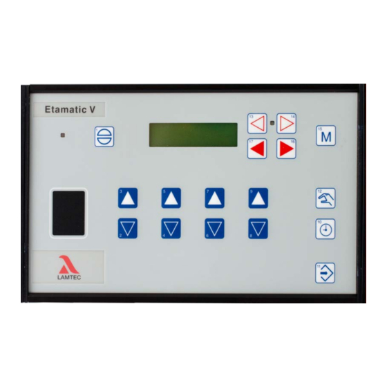
Page 9: Operator Device
Description Operator Device UEAN PARA O AUTO EINS SPLO Select operating modes: Select operating parameters: Status Firing rate rating Setpoint Actual value feedback Setpoint feedback Dig- ital inputs Display change: -Compound - Flame inten- sity... - Page 10 -compound -flame intensity ** UEAN monitoring processor display PARA parameterisation AUTO automatic EINS clear memory SPLO * only available, if activated in the parameter section ** only available with ETAMATIC V / ETAMATIC V S the option "Integrated Flame Monitor"...
-
Page 11: Operation
Press keys 3 and 2 to browse through the fault history. NOTICE If it is certain that the ETAMATIC V has carried a voltage at all times since the last fault, it is possible, that from the present output of the running time counter and the current time, to de- termine at which time the fault occurred. -
Page 12: Resetting O Errors
30 sec are stored. They are only stored in the EEPROM once the fault is cleared up or the ETAMATIC V leaves the operating mode or control or base firing rate. How to switch the Display... -
Page 13: Operation And Display Of The O2 Trim
Operation Operation and Display of the O2 Trim Press key 15 once, to switch the display to O -trim. When you have switched to "Status", the display shows the O actual value and O setpoint value. The display shows the values in brackets, if O trim is deactivated. -
Page 14: Call Up The Checksums And Safety Times
NOTICE The total counter refers to the ETAMATIC V 's running time. It starts timing as soon as the unit is connected to a voltage source (this also provides the basis for the fault history). The individual running time counters refer to the burner's running time. They start timing as soon as the burner is in operation with the relevant curve set (flame signal is present). -
Page 15: Internal Burner Firing Rate Controller
Moving Screen "Actual Temperature is too high" Press key 12 HAND to override this and start the ETAMATIC V, if the maximum tem- perature has not exceeded. Press key 12 HAND again to switch back to automatic mode. -
Page 16: Thermostat And Control Range
"Manual" again You also may switch the ETAMATIC V to "Manual Control" with the terminals. By short-circu- iting the PT 100 signal (e.g. bridge terminal 19 and 20) the burner firing rate controller is switched off. -
Page 17: Meaning Of The Display
Internal Burner Firing Rate Controller NOTICE Only use manual control while monitoring the system. Meaning of the Display Display in "FIRING RATE" switch position setpoint actual value regular firing internal rate input firing rate Display in mode "MANUAL" regular firing internal firing actual value rate input... -
Page 18: Appendix
Description → READY (signal on terminal 58) ZÜ → IGNITION POSITION or IGNITION → SETTING/IGNITION position (same as IGNITION, but ETAMATIC V on SETTING) → BASE FIRING RATE → SETTING/BASE FIRING RATE” (as BASIC FIRING RATE, but ETA- MATIC V on SETTING) →... -
Page 19: Fault Codes
Appendix Fault Codes The letter "H" preceding a fault code indicates that the main processor has discovered the cause of the fault. A "Ü" preceding the code indicates that the monitoring processor has activated the fault. A * indicates that a re-start is permitted for this fault. A flashing fault LED indicates that a re- start is to be initiated within a short period. - Page 20 Appendix Fault Restart according to Description Code EN676 The flame signal extinguishes during the first safety time H/Ü Check flame stability. Check set pilot burner. Check flame sensor. ETAMATIC: Check Jumper. The flame signal extinguishes during the second safety time H/Ü...
- Page 21 Appendix Fault Restart according to Description Code EN676 Internal fault: Internal communication fifo has overflowed The fault can occur during an internal self-test. Reset the fault. In the process, switch the mains voltage off and on again if neces- sary. Check all fuses in the device.
- Page 22 For more details, see the "Protected data record" description in the remote control software. If this is not possible, you must order a preprogrammed EEPROM from LAMTEC. When ordering, you must enter the device number and software checksums. Only in this way are mix-ups excluded. For the address, see the overleaf of this publica- tion.
- Page 23 If fault messages are constantly appearing one after the other the EPROM pro- gramme is possibly defective. Request a new programme EPROM from LAMTEC with the precise specification of the respective purchase order number, sales order number, and commission of the device.
- Page 24 Appendix Fault Restart according to Description Code EN676 RAM-Test detected error H/Ü Fault during an internal self-test. Reset the fault; switch the mains voltage off and on again if necessary. Check all fuses in the device. Check the curve points of the main and monitoring processors for irregularities. ...
- Page 25 Appendix Fault Restart according to Description Code EN676 The correction is outside the permissible range. Channel: 1 Ü The monitoring processor checks whether the current correction values lie within the set range. Check the correction range. If fault messages are constantly appearing one after the other → exchange the device or respective card.
- Page 26 For more details, see the "Protected data record" description in the remote control software. If this is not possible, you must order a preprogrammed EEPROM from LAMTEC. When ordering, you must enter the device number and software checksums. Only in this way are mix-ups excluded. For the address, see the overleaf of this publica-...
- Page 27 Appendix Fault Restart according to Description Code EN676 Potentiometer faulty, feedback changing too quickly: channel 1 H/Ü The return values of a three-point-step servo output change faster than specified as maximum in parameters 12-16. Check the wiring; check the potentiometers for short circuit. It is possible that the range limit switch is set higher than the end of the range of the potentiometer.
- Page 28 Appendix Fault Restart according to Description Code EN676 >88 the same as P 151, but channel: 2 H/Ü See S151 >88 the same as P 151, but channel: 3 H/Ü See S151 >88 the same as P 151, but channel: 4 H/Ü...
- Page 29 Appendix Fault Restart according to Description Code EN676 1st monitoring band under range too long. Channel: 1 1st monitoring band under range too long. Channel: 2 1st monitoring band under range too long. Channel: 3 1st monitoring band under range too long. Channel: 4 1st monitoring band under range too long.
- Page 30 Appendix Fault Restart according to Description Code EN676 Different status of ignition position relay >88 Invalid curve selection (no signals) >88 Invalid curve selection (several signals) Shut down from O controller (1) or CO controller (2) : Initially, the time from parameter P904 "O trim active after ignition in seconds"...
- Page 31 Appendix Fault Restart according to Description Code EN676 Different point number at programming Ignition position was left in ignition mode. Channel: 1 Ignition position was left in ignition mode. Channel: 2 Ignition position was left in ignition mode. Channel: 3 Ignition position was left in ignition mode.
- Page 32 Appendix Fault Restart according to Description Code EN676 See S500 Internal comparison: relay output terminal 67 not dropping out. See S500 Internal comparison: relay output terminal 43 or 68 (ETAMATIC) not dropping out. See S500 Internal comparison: relay output terminal 16 or 65 (ETAMATIC) not dropping out.
- Page 33 Appendix Fault Restart according to Description Code EN676 Terminal 60 not connected or fuse F5 defective. Check whether terminals 26 and 60 are supply by the same phase. See S500 TRIAC selftest : all TRIACS are not supplied with voltage! See S500 TRIAC selftest : main gas 1 is currentless If a test current is flowing during the TRIAC self test and no test current is at the ter-...
- Page 34 Appendix Fault Restart according to Description Code EN676 >88 Oil safety chain dropping. >88 Gas pressure too low Gas pressure too high. Air pressure signal missing. F.A. safety interl. chain gets OFF Flame is blown away during blow out of oil lance Ignition flame goes out in standby operation Continuous ignition flame goes out under operation Oil circulation: Temperature does not rise up within 45 sec.
- Page 35 Appendix Fault Restart according to Description Code EN676 Ignition valve open too long Fuel valves open in maintenance mode Ignition process taking too long Gas valves open when burning oil Oil valves open when burning gas Main gas 2 open without main gas 1 Main gas 1 illegally open Main gas valves and ignition valve open too long Ignition process taking too long (without pilot burner)
- Page 36 Remote-fault-reset happens within a too short distance EN 14459 permits a remote unlocking only 4 x within 15 minutes. The fault release is monitored by the remote control software, LAMTEC system bus, and field bus (parameter 19). When exceeded, fault deactivation H889 is gen- erated and additional remote fault releases are ignored.
- Page 37 Appendix Fault Restart according to Description Code EN676 Error in self-test sequencer. H/Ü Fault during an internal self-test. Reset the fault; switch the mains voltage off and on again if necessary. If fault messages are constantly appearing one after the other exchange the device or respective card.
- Page 38 Check all fuses in the device. If fault messages are constantly appearing one after the other exchange the device or respective card. Curve set adjustment via LAMTEC SYSTEM BUS, selftest recognizes fault Error in reference, channel: 1 Ü Fault during an internal self-test.
- Page 39 Appendix Fault Restart according to Description Code EN676 Relay driver self-test : output terminal 11 or 66 (ETAMATIC) faulty. H/Ü Fault during an internal self-test. Reset the fault; switch the mains voltage off and on again if necessary. Check all fuses in the device. If fault messages are constantly appearing one after the other ...
- Page 40 This fault occurs when the "Burner On" and "Pre-venting" signals occur in the wrong order or too quickly in sequence during the postpurge time in the case of devices without a burner sequencer (VMS / ETAMATIC V). No fault occurs if the devices switches to the "Ready" (BE) mode downstream of the "Burner On"...
-
Page 41: Calling Up The Condition Of The Digital Inputs
Appendix Calling Up the Condition of the Digital Inputs Switch to "digital inputs" with keys 16 and 17 Meaning of the digital inputs of the ETAMATIC V Signal applies Signal does not apply... -
Page 42: Process Sequence Charts
Appendix Process Sequence Charts Caption for the Process Sequence Charts... - Page 43 Appendix Condition, any Stand-by Running time actuator Pre-purge period Running time actuator ignition position Delay of the recirculation valve Base firing rate Operation period Regular operation Post-ventilating time 0s - 255s, adjustable * If the channels run close after a shut down, the pre-purge signal will be ignored until the channels have reached their lower threshold.
-
Page 44: Connecting Diagram
Appendix Connecting Diagram Fig. 6-2 Connecting diagram ETAMATIC V... - Page 45 Appendix Fig. 6-3 connecting diagram...
-
Page 46: Switch And Key Combinations
15 / F4 (M) twice Without integral flame monitoring, the dis- play shows "---%" Mode switching with O trim Automatic press key 15 (M) twice ETAMATIC V mode O trim Status trim Mode O trim, press key 11 (Enter) to acknowledge... - Page 47 Appendix Action Display Mode Buttons / Other Calling up text messages Status trim press key 11 (Enter) Display monitoring mode Automatic hold and press 13 Setting Change in mode T firing rate key 11 (Enter), Key 5 value Set base firing rate to finish: set the correction value to neutral or control mode value and press key 4)
-
Page 48: Technical Data
The parasitic capacitance of the lead connected to the digital inputs may not exceed 2.2μF as Inputs a result of the ETAMATIC V self-tests. The lead length should be limited to 100 m. Since the digital inputs are for 24V DC, suitable contacts for that voltage should be used (hard silver or... - Page 49 State Input Number of program unlimited cycles Interfaces – 1 serial interface on 25-pole Sub-D-connector, addressable via LAMTEC adapter only (Dongle 663P0600)(RS 232) – 1 interface on 9-pole Sub-D-connector WARNING! Using the interface without the adapter may damage the device.
- Page 50 Appendix Dimensions ETAMATIC V (l x w x d) 144 x 240 x 142 Installation depth 125 mm Weight 2,3 kg Protection class to DIN 10 050 IP 40 Installation ETAMATIC V Panel mounting Position of use Fig. 6-4 Minimum distances in the case of several cut-outs Fig.
- Page 51 F3 main gas 1 F4 main gas 2 F5 ignition transformer, fan, ignition valves, oil pump, fault S1 9-pole Sub-D connector for LAMTEC SYSTEM BUS S2 communications interface PC connection is possible only with LAMTEC interface adapter! Fig. 6-7 Rear view...
- Page 52 Appendix Fig. 6-9 Dimensional drawing FS60 for flame sen- Fig. 6-10 Dimensional drawing ring FFS06, FFS08 sor FFS06, FFS08 (DLT7660) (DLT7660) Fig. 6-11 Flame sensor FFS05, FFS07 (replaced by FFS05, connecting cable FFS07 includes 1 rs cord extra) Description type plate grounding M4 (Pozidriv 2) incidence of light bend radius of the FM wire min.
-
Page 53: Declaration Of Conformity
Appendix Declaration of Conformity... - Page 54 Appendix...
- Page 55 Appendix...
- Page 56 The information in this publication is subject to technical changes. LAMTEC Meß- und Regeltechnik für Feuerungen GmbH & Co. KG Wiesenstraße 6 D-69190 Walldorf Telefon: +49 (0) 6227 6052-0 info@lamtec.de Telefax: +49 (0) 6227 6052-57 www.lamtec.de Printed in Germany | Copyright 2016...
Need help?
Do you have a question about the ETAMATIC V and is the answer not in the manual?
Questions and answers