Sign In
Upload
Manuals
Brands
Lamtec Manuals
Control Unit
ETAMATIC
Lamtec ETAMATIC Manuals
Manuals and User Guides for Lamtec ETAMATIC. We have
5
Lamtec ETAMATIC manuals available for free PDF download: Manual, Quick Reference
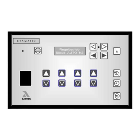
Lamtec ETAMATIC Manual (152 pages)
Brand:
Lamtec
| Category:
Controller
| Size: 6.65 MB
Table of Contents
Table of Contents
3
1 General Information
7
Validity of These Instructions
7
Variants - Device Configuration
8
2 Safety
10
For Your Safety
10
Associated Automatic Flame Guard
11
3 Brief Description
12
Display and Operational Controls
13
4 Operating Description
14
Starting with Pilot Burner
14
Starting Without Pilot Burner
14
5 Commissioning
15
Before Commissioning
15
Basic Settings
15
Password Entry
15
How to Change the Password
15
Edit Parameter
16
Select Language
16
Character of the Output Channels
17
Start with or Without Pilot Burner
19
Pre-Purge Period
21
Recirculation Delay
21
Deactivate Firing Rate Control Unit
22
Running Time of the Regular Firing Rate Input with TPS-Input
22
Minimum Running Time of the Fuel/Air Ratio Control
23
Post-Purge Time
23
Delaytime of the Air Dampers During Pre-Purge
23
Parameters of the Interface
24
Deactivate Leakage Test
25
Set Pilot Burner (Maintenance Mode)
26
Automatic Restart after Failure
26
Burner Firing Rate Controller
27
Enter Set Point Values
27
Control Range
28
Setting the Control Thermostat
29
Controller Parameters
29
Outside Temperature Limits
29
Display of the Units of the Burner Firing Rate Controller Values
30
Display Range in Bar
30
Setting
31
Setting the Limit Switches of the Motors
31
Adjusting Control Elements
31
Enter the Curve
31
Clear Memory
32
Programming the Ignition Point
32
Programming the Base Firing Rate
32
Programming the 3Rd up the 10Th Point
32
Saving Curve
33
Changing Points
33
Saving Changes
33
Re-Enter Range Limits
34
Fault
34
Reading Faults
34
Resetting Faults
34
Recalling Fault History
35
Calling up the Hour Counter
35
Calling the Checksums
36
6 Trim
37
What Happens if a Fault Occurs in the O Trim
37
How to Switch the Display
37
Air Deficiency Failure
37
Resetting O Errors
37
Calling Fault History O Trim
38
Automatic Function Monitoring During Operation
38
Test During Burner Start
38
O 2 Monitoring Band
39
O 2 Limit Curve
39
Dynamic Probe Test
40
Control Strategy
41
Connecting the O 2 Measurement Device
42
Operation and Display of the O2 Trim
43
Display and Interpretation of the Operating Modes
43
Calling up O 2 Trim Text Messages
44
Commissioning
44
Setting the Correction Range and the Correction Mode
44
Available Correction Modes
45
Correctiontype1
45
Correction Type 2
45
Setting the Correction Range
46
Calling up the Set Correction Mode
47
Checking the Combustion Limit Values
47
O 2 Curve Input
48
Changing O Setpoints
48
Manual Calculating and Setting of the Control Parameters
49
Guidelines
49
7 Internal Burner Firing Rate Controller
53
Purpose
53
Brief Description
53
Range Limits
53
Moving Screen "Actual Temperature Is too High
53
Enter Setpoint of Firing Rate Controller
54
Input Signals
54
Operating Description
55
Steam Pressure
55
Control by Atmospheric Condition
55
Setpoint Changeover
56
Start-Up Sequence
57
Thermostat and Control Range
58
Manual Control
60
Meaning of the Display
60
How to Adjust the Burner Firing Rate Controller
60
Control Range
61
Checking of the Safety Limiter
61
8 Control Mode
62
Aides for Setting
63
Valve Leakage Test
65
Valve Leakage Test Flow Chart
66
Calculation Example
66
Calculation of Gas Pressure Switching Point > Min
67
En13611:2012)
68
Standby
69
Standby Mode
69
Switching into Standby Mode Via LSB Module
71
9 Appendix
72
Mode Abbreviations Used
72
Flame Monitoring
73
Integral Flame Monitoring (Option)
73
Purpose
73
Characteristics Flame Sensor
73
Self Monitoring
74
General Information of the Optical Flame Monitoring
75
Optical Flame Sensors
75
Switching to Display the Flame Intensity
75
Avoiding EMC Effects
76
Fault Codes
77
Calling up the Condition of the Digital Inputs
99
Tips and Tricks
100
Set Pilot Burner
100
Post-Measurement of Safety Times
100
Process Sequence Charts
101
Connection Diagrams
109
Connection Examples Regular Firing Rate Input
111
Connections in Non Grounded Power Line Networks
112
Fan Force-Open During Fault
112
Connection Flame Scanner
113
Lamtec System Bus (Lsb)
115
Configuration of the Processor Board
115
LSB Connection
115
LAMTEC SYSTEM BUS Plug
118
Modem for Remote Control
120
Inernal Connecting Diagram of the Control Output Device
121
Interlock Chain Wiring Via 230 V
121
Valve Leakage Test Venting over the Roof
122
Switch- and Key Combinations
124
Sensor
125
Direct Connection to R. P. M. Sensor
125
Selection of a Suitable R. P. M. Sensor
128
Circuit Proposal 3-Wired Speed Sensor with Higher Power Supplay Voltage
130
External Switching of the Fuel Motors/ Valves
131
Feedback at Three-Point-Step Channels
133
Connect with Positive Locking
133
Fail-Safe Feedback
133
Examples of Potentiometers and Motors
133
Changing Control Drives / Potentiometers
135
How to Replace a Servo Motor
135
How to Replace a Potentiometer
135
Changing Eproms
135
Wiring Notes
137
Shields Connection
137
PE Busbar
137
Control Cabinet Wiring
138
Run to Shut-Off Limits
138
Tolerance Limit in Direction Air Deficiency
139
Example of a Protocol of the Parameter Settings of the Monitoring Bands
141
Technical Data
142
ETAMATIC Without Internal Flame Monitoring
145
Dimensions and Weight
146
Declaration of Conformity
150
Advertisement
Lamtec ETAMATIC Manual (136 pages)
Sensors and Systems for Combustion Engineering
Brand:
Lamtec
| Category:
Control Unit
| Size: 4.42 MB
Table of Contents
Table of Contents
3
1 General Information
8
Validity of These Instructions
8
Variants - Device Configuration
9
2 Safety
11
German Law on Device Safety
11
For Your Safety
12
Associated Automatic Flame Guard
13
3 Brief Description
14
Display and Operational Controls
15
4 Operating Description
16
Starting Without Pilot Burner
16
Starting with Pilot Burner
16
5 Commissioning
17
Before Commissioning
17
Basic Settings
17
Password Entry
17
Select Language
17
Character of the Output Channels
18
Start with or Without Pilot Burner
20
Pre-Ventilation Period
22
Recirculation Delay
22
Deactivate Load Control Unit
23
Running Time of the Regular Firing Rate Input with TPS-Input
23
Minimum Running Time of the Compound
23
Post-Ventilation Time
24
Delaytime of the Air Dampers During Pre-Ventilation
25
Parameters of the Interface
26
Deactivate Leakage Test
26
Set Pilot Burner (Maintenance Mode)
27
Automatic Restart after Failure
28
Burner Firing Rate Controller
29
Setting
33
Setting the Limit Switches of the Motors
33
Adjusting Control Elements
33
Programming the Ignition Point
34
Programming the Base Load
34
Programming the 3Rd up the 10Th Point
35
Saving Curve
35
Changing Points
35
Saving Changes
35
Fault
36
Reading Faults
36
Resetting Faults
36
Recall Fault History
36
6 O2-Control
37
What Happens if a Fault Occurs in the O2 Regulation
37
How to Switch the Display
37
Air Deficiency Pertubation
37
Resetting O2-Errors
37
Calling Fault History O2-Controller
38
How to Change the Password
38
How to Switch the Display
38
Automatic Function Monitoring During Operation
39
Test During Burner Start
39
O2 Monitoring Band
39
O2 Boundary Curve
40
Dynamic Probe Test
40
Control Strategy
41
Connecting the O2 Measurement Device
42
Operation and Display of the O2-Controller
43
Display and Interpretation of the Operating Modes
43
Calling up O2 Controller Text Messages
44
Commissioning
44
Setting the Correction Range and the Correction Mode
44
Available Correction Modes
44
Correction Type 2
45
Setting the Correction Range
45
Calling up the Set Correction Mode
46
Checking the Combustion Boundary Values
46
O2 Curve Input
47
Calling up Running Time Meter
51
Calling up the Checksum
51
Re-Enter Range Limits
52
7 Internal Burner Firing-Rate Controller
53
Purpose
53
Brief Description
53
Limit Ranges
53
Light Writing "Actual Temperature Is too High
53
Enter Setpoint of Power Control
53
Input Signals
54
Operating Description
54
Steam Pressure
54
Control by Atmospheric Condition
55
Set Point Changeover
55
Start-Up Sequence
56
Thermostat and Control Range
57
Manual Control
59
Meaning of the Display
59
How to Adjust the Burner-Firing-Rate Controller
59
Control Range
60
Checking of the Safety Limiter
60
8 Control Mode
61
Aides for Setting
62
Leakage Test
64
Leakage Test Flow Chart
65
Calculation Example
66
Standby
67
9 Appendix
70
Mode Abbreviations Used
70
Flame Monitoring
71
Integral Flame Monitoring (Option)
71
General Information of the Optical Flame Monitoring
72
Optical Flame Sensors
73
Avoiding EMC Effects
73
Error Codes
75
Aides
82
Calling up the Condition of the Digital Inputs
88
Tips and Tricks
89
Set Pilot Burner
89
Post-Measurement of Safety Times
89
Process Sequence Charts
90
Connection Diagrams
98
Connection Examples Regular Firing Rate Input
100
Connection Flame Monitor and External Firing Rate Controller
101
Lamtec System Bus (Lsb)
102
Configuration of the Processor Board
102
LSB Connection
102
LAMTEC SYSTEM BUS Plug
105
Modem for Remote Control
107
Inernal Connecting Diagram of the Control Output Device
108
Exhaust of Test Line over the Roof
109
Switch- and Key Combinations
110
Sensor
111
Direct Connection of the R. P. M. Sensor
111
Selection of the Suitable R. P. M. Sensor
113
External Switching of the Fuel Motors/ Valves
115
Feedback at Three-Point-Step Outputs
116
Joining with Positive Locking
116
Fail-Safe Feedback
116
Examples of Potentiometers
116
Changing Control Drives / Potentiometers
117
How to Replace a Servo Motor
117
How to Replace a Potentiometer
118
Changing Eproms
118
Wiring Notes
120
Connection of the Shields
120
PE Bus Rail
120
Control Cabinet Wiring
120
Run to Shut-Off Limits
121
Tolerance Limit in Direction Air Deficiency
122
Example of a Protocol of the Parameter Settings of the Monitoring Bands
124
Technical Data
125
ETAMATIC Without Internal Flame Monitoring
128
Lamtec ETAMATIC Quick Reference (62 pages)
Brand:
Lamtec
| Category:
Control Unit
| Size: 1.24 MB
Table of Contents
German
3
Channel 1 OPEN
3
Table of Contents
4
Allgemeine Hinweise
6
Gültigkeit dieser Anleitung
6
Normen
6
Kurzbeschreibung
6
Geräte-Sicherheitsgesetz
9
Ablaufbeschreibung ETAMATIC
11
Start ohne Zündbrenner
12
Start mit Zündbrenner
12
Störung Ablesen
13
Störung Rücksetzen
13
Störungshistorie Abrufen
13
O -Regler
14
Was Passiert bei Störung O -Regler
14
O -Störung Rücksetzen
14
Störungshistorie O -Regelung Abrufen
15
Anzeige Umschalten
15
Bedienung und Anzeige O -Regelung
16
Anzeige und Bedeutung der Betriebsmodi
17
Textmeldungen O -Regelung Abrufen
17
Betriebsstundenzähler Abrufen
18
Abrufen der Checksummen und Sicherheitszeiten
19
Interner Leistungsregler
20
Verwendungszweck
20
Kurzbeschreibung
20
Grenzbereiche
20
Laufschrift "Isttemperatur zu Hoch
20
Leistungsreglersollwert Eingeben
21
Leistungsreglersollwert über Tastenkombination Verändern
21
Thermostat und Regelbereich
22
Handsteuerung
23
Anhang
24
Bedeutung der Modi
24
Integrierte Flammenüberwachung
25
Verwendungszweck
25
Kennwerte Flammenfühler
25
Eigenüberwachungsprinzip
26
Umschaltung auf Anzeige Flammenintensität
26
Zustand der Digitalen Eingänge Abrufen
41
Bedeutg. Digitale Eingangsanzeige ETAMATIC
41
Ablaufdiagramme
42
Anschlussbild ETAMATIC/ETAMATIC S
48
Schalter- U. Tastenkombinationen
49
Schalter- U. Tastenkombinationen der O -Regelung
50
Technische Daten
51
ETAMATIC ohne Internen Flammenwächter
57
Rückansicht
59
Flammenfühler FFS06 und FFS05
59
Konformitätserklärung
60
English
6
General Information
6
Validity of These Instructions
6
Standards
6
Brief Description
6
Legislation on the Safety of Appliances
9
ETAMATIC Operating Description
11
Starting Without Pilot Burner
12
Starting with Pilot Burner
12
Read off Fault
13
Reset Fault
13
Recall Fault History
13
O Trim
14
What Happens if a Fault Occurs in the O Trim
14
Resetting O Errors
14
Calling up O Regulation Error History
15
Display Switching
15
Operation and Display O Trim
16
Display and Interpretation of Operating Modes
17
Calling up O Trim Test Messages
17
Call up Running Time Counter
18
Call up the Checksums and Safety Times
19
Internal Power Control Units
20
Purpose
20
Brief Description
20
Limit Ranges
20
Operating Message: "Actual Temperature too High
20
Enter Setpoint of Power Control
21
Change Setpoint of Power Control
21
Thermostat and Control Range
22
Manual Control
23
Appendix
24
Mode Abbreviations Used
24
Integral Flame Monitoring
25
Applications
25
Flame Sensor Characteristics
25
Self-Monitoring Principle
26
Switch Display to Flame Intensity
26
Interpreting the Etamatic's Digital Input Display
41
Significance of ETAMATIC Digital Input Display
41
Process Sequence Charts
46
ETAMATIC / ETAMATIC S Wiring Diagrams
47
Switch and Key Combinations
49
Switch and Key Combinations for O Trim
50
Technical Data
51
ETAMATIC Without Internal Flame Monitor
57
Rear View
59
Flame Sensor FFS06 and FFS05
59
Declaration of Conformity
60
Finnish
6
Yleisiä Ohjeita
6
TäMän Käyttöohjeen Tarkoitus
6
Laki Laitteiden Turvallisuudesta
9
Etamaticin Toiminnan Kuvaus
11
Käynnistys Ilman Sytytyspoltinta
12
Käynnistys Sytytyspolttimella
12
Häiriön Lukeminen
13
Häiriön Palautus Alkutilaan
13
Häiriöhistorian Kutsuminen
13
Übernahme
13
O -Säädin
14
Mitä Tapahtuu Häiriön Ilmaantuessa O -Säätimeen
14
O -Häiriön Palautus Alkutilaan
14
O -SääDön Häiriöhistorian Kutsuminen
15
Näytön Vaihtaminen
15
O -SääDön Käyttö Ja Näyttö
16
Toimintatilojen Merkitys Ja Näyttö
17
Tekstiviestit O -SääDön Kutsuminen
17
Käyttötuntilaskimen Kutsuminen
18
Tarkastussummien Ja Turva-Aikojen Kutsuminen
19
Tehonsäätimen Asetusarvon Syöttäminen
21
Tehonsäätimen Asetusarvon Muuttaminen Painikeyhdistelmällä
21
Termostaatti Ja Säätöalue
22
Käsiohjaus
23
Liite
24
Toimintatilojen Merkitykset
24
Integroitu Liekinvartija
25
Käyttötarkoitus
25
Liekkianturin Ominaisarvot
25
Itsevalvonnan Periaate
26
Vaihto Liekkivoimakkuuden Näyttöön
26
Störcodes
27
Fault Codes
27
Häiriökoodit
27
Hilfen
34
Aides
34
Ohjeita
34
Digitaaliottojen Tilanäytön Kutsuminen
41
Etamaticin Digitaaliottojen Näytön Merkitys
41
Kulkukaaviot
42
Liitäntäkaavio ETAMATIC/ETAMATIC S
47
Kytkin -Ja Painikeyhdistemät
49
O -SääDön Kytkin -Ja Painikeyhdistelmät
50
Teniset Tiedot
51
ETAMATIC Ilman Integroitua Liekinvartijaa
57
Takapuolen Kuva
59
Liekkianturit FFS06 Ja FFS05
59
Selvitys Standardinmukaisuudesta
60
Advertisement
Lamtec ETAMATIC Quick Reference (62 pages)
Enduser
Brand:
Lamtec
| Category:
Controller
| Size: 0.71 MB
Table of Contents
English
2
O -Regulator
2
Table of Contents
4
General Information
6
Validity of These Instructions
6
Standards
6
Brief Description
6
Legislation on the Safety of Appliances
9
ETAMATIC Operating Description
11
Starting Without Pilot Burner
12
Starting with Pilot Burner
12
Read off Fault
13
Reset Fault
13
Recall Fault History
13
O Trim
14
What Happens if a Fault Occurs in the O Trim
14
Resetting O Errors
14
Vad Händer VID Fel I O -Regulator
14
Återställ O -Fel
14
Calling up O Regulation Error History
15
Display Switching
15
Anropa Felhistorik O -Reglering
15
Växla Indikering
15
Operation and Display O Trim
16
Hantering Och Visning, -Regulator
16
Display and Interpretation of Operating Modes
17
Calling up O Trim Test Messages
17
Anropa Textmeddelanden -Reglering
17
Call up Running Time Counter
18
Call up the Checksums and Safety Times
19
Anropa Checksummor Och Säkerhetstider
19
Internal Power Control Units
20
Purpose
20
Brief Description
20
Limit Ranges
20
Operating Message: "Actual Temperature too High
20
Enter Setpoint of Power Control
21
Change Setpoint of Power Control
21
Thermostat and Control Range
22
Manual Control
23
Appendix
24
Mode Abbreviations Used
24
Integral Flame Monitoring
25
Applications
25
Flame Sensor Characteristics
25
Self-Monitoring Principle
26
Switch Display to Flame Intensity
26
Interpreting the Etamatic's Digital Input Display
41
Significance of ETAMATIC Digital Input Display
41
Process Sequence Charts
46
ETAMATIC / ETAMATIC S Wiring Diagrams
47
Switch and Key Combinations
49
Switch and Key Combinations for O Trim
50
Technical Data
51
Tekniska Data
51
ETAMATIC Without Internal Flame Monitor
57
ETAMATIC Utan Intern Flamdetektor
57
Rear View
59
Flame Sensor FFS06 and FFS05
59
Baksidesbild
59
Flamsensor FFS06 Och FFS05
59
Declaration of Conformity
60
Konformitetsförklaring
60
German
6
Allgemeine Hinweise
6
Gültigkeit dieser Anleitung
6
Normen
6
Kurzbeschreibung
6
Geräte-Sicherheitsgesetz
9
Ablaufbeschreibung ETAMATIC
11
Start ohne Zündbrenner
12
Start mit Zündbrenner
12
Störung Ablesen
13
Störung Rücksetzen
13
Störungshistorie Abrufen
13
O -Regler
14
Was Passiert bei Störung O -Regler
14
O -Störung Rücksetzen
14
Störungshistorie O -Regelung Abrufen
15
Anzeige Umschalten
15
Bedienung und Anzeige O -Regelung
16
Anzeige und Bedeutung der Betriebsmodi
17
Textmeldungen O -Regelung Abrufen
17
Betriebsstundenzähler Abrufen
18
Abrufen der Checksummen und Sicherheitszeiten
19
Interner Leistungsregler
20
Verwendungszweck
20
Kurzbeschreibung
20
Grenzbereiche
20
Laufschrift "Isttemperatur zu Hoch
20
Leistungsreglersollwert Eingeben
21
Leistungsreglersollwert über Tastenkombination Verändern
21
Thermostat und Regelbereich
22
Handsteuerung
23
Anhang
24
Bedeutung der Modi
24
Integrierte Flammenüberwachung
25
Verwendungszweck
25
Kennwerte Flammenfühler
25
Eigenüberwachungsprinzip
26
Umschaltung auf Anzeige Flammenintensität
26
Störcodes
27
Fault Codes
27
Hilfen
34
Aides
34
Zustand der Digitalen Eingänge Abrufen
41
Bedeutg. Digitale Eingangsanzeige ETAMATIC
41
Ablaufdiagramme
42
Anschlussbild ETAMATIC/ETAMATIC S
48
Schalter- U. Tastenkombinationen
49
Schalter- U. Tastenkombinationen der O -Regelung
50
Technische Daten
51
ETAMATIC ohne Internen Flammenwächter
57
Rückansicht
59
Flammenfühler FFS06 und FFS05
59
Konformitätserklärung
60
Swedish
6
Apparatsäkerhetslagstiftning
6
Giltighet För Denna Manual
6
Processbeskrivning ETAMATIC
11
Start Utan Tändbrännare
12
Start Med Tändbrännare
12
Läs Av Fel
13
Återställ Fel
13
Anropa Felhistorik
13
Ange Effektregleringsbörvärde
21
Ändra Effektregleringsbörväre Via Tangentkombinationr
21
Termostat Och Regleringsintervall
22
Manuell Styrning
23
Bilaga
24
Betydelse Av Lägena
24
Inbyggd Flambevakning
25
Ändamål
25
Karakteristika Flamsensor
25
Självbevakningsprincip
26
Växling Till Visning Av Flamintensitet
26
Felkoder
27
Hjälp
34
Anropa Status För Digitala Ingångar
41
Betydelse Av Visning Digitala Ingångar ETAMATIC
41
Flödesdiagram
42
Anslutningsbild ETAMATIC/ETAMATIC S
47
Omkopplar- Och Tangentkombinationer
49
Omkopplar- Och Tangentkombinationer O -Reglering
50
French
9
Prescriptions de Sécurité Sur Les Appareils
9
Lamtec ETAMATIC Quick Reference (26 pages)
Endusers
Brand:
Lamtec
| Category:
Control Unit
| Size: 1.44 MB
Table of Contents
Table of Contents
3
1 General Information
4
Validity of These Instructions
4
2 Safety
5
For Your Safety
5
3 Brief Description
6
4 Operating Description
7
Starting with Pilot Burner
7
Starting Without Pilot Burner
7
5 Fault
8
Reading Faults
8
Resetting Faults
8
Recalling Fault History
8
6 Operation
9
CO/O 2 Control
9
What Happens if a Fault Occurs in the O Trim
9
Resetting O 2 Errors
9
Calling Fault History O Trim
10
Calling CO/O Control Text Messages
10
Display and Interpretation of the Operating Modes
11
Displaying the Running Time Meter
12
Calling the Checksums
13
7 Internal Burner Firing Rate Controller
14
Purpose
14
Moving Screen "Actual Temperature Is too High
14
Changing Setpoint of Burner-Firing-Rate Controller
14
Manual Control
15
Meaning of the Display
15
8 Appendix
16
Mode Abbreviations Used
16
Fault Codes
17
Calling up the Condition of the Digital Inputs
21
EU Declaration of Conformity
23
Advertisement
Related Products
Lamtec ETAMATIC S
Lamtec ETAMATIC OEM
Lamtec ETAMATIC S OEM
Lamtec ETAMATIC V
Lamtec ETAMATIC V S
Lamtec 663R0932
Lamtec Categories
Control Unit
Controller
Transmitter
Industrial Equipment
Control Systems
More Lamtec Manuals
Login
Sign In
OR
Sign in with Facebook
Sign in with Google
Upload manual
Upload from disk
Upload from URL