Sealite SL-C310 Series Installation & Service Manual
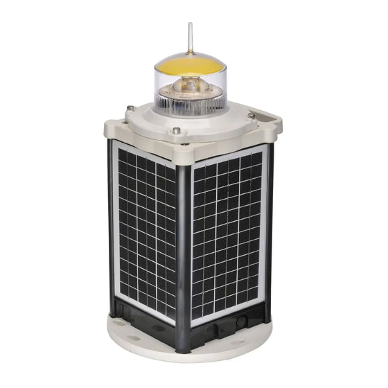
Compact 3-5nm+ solar marine lantern
Hide thumbs
Also See for SL-C310 Series:
- Installation & service manual (36 pages) ,
- Installation and service manual (16 pages) ,
- Installation & service manual (36 pages)
Table of Contents
Advertisement
Quick Links
Advertisement
Table of Contents

Related Manuals for Sealite SL-C310 Series


Summary of Contents for Sealite SL-C310 Series
- Page 1 SL-C310 Compact 3-5NM+ Solar Marine Lantern INSTALLATION & SERVICE MANUAL V5.0...
- Page 2 Version No. Description Date Author Approved Update: Contact details April 2016 J. Dore M.Nicholson Update: Flash Code Tables June 2017 A.Dixon M.Nicholson Update: products images,Drawings October 2018 M.Nicholson Update to Flash Code Tables May 2019 A.Gazzola M.Nicholson Minor amendment - flash code May 2019 M.Dutka M.Nicholson...
-
Page 3: Table Of Contents
Optional Iridium Satellite Monitoring & Control ................. Page 29 Optional GSM Monitoring & Control System ................. Page 30 Lantern Status..............................Page 31 Maintenance & Servicing..........................Page 32 Trouble Shooting..............................Page 35 Sealite LED Light Warranty......................... Page 35 Latest products and information available at www.sealite.com... -
Page 4: Introduction
ISO9001:2015 quality management system. Sealite lanterns comply with requirements of the US Coast Guard in 33 CFR part 66 for Private Aids to Navigation. By taking a few moments to browse through this booklet, you will become familiar with the versatility of your lantern, and be able to maximize its operating function. -
Page 5: C310 Models
The system can also be configured to send out alarm messages to designated phone numbers. Users can also have alarms and reports sent to designated email addresses. These models have an IR sensor which also allows them to be operated via Sealite’s IR remote control. -
Page 6: Product Components
These components are securely packaged within protective wrap, in a carton and shipped to you. Please check that ALL of these components are included with your order and contact your Sealite representative as soon as possible if anything is missing. -
Page 7: Technical Specifications
Ingress Protection IP68 Intellectual Property Trademarks SEALITE ® is a registered trademark of Sealite Pty Ltd Warranty * 3 years • 50mm pole mount adapterplate • Satellite Communications • GSM Cell-Phone Options Available Latest products and information available at www.sealite.com... - Page 8 Technical Illustrations SL-C310 Base Model Ø 234 Compact Standard Ø 200 120° Base Ø 234 Compact Standard Extended SL-C310 with Ø 200 Satellite Module Ø 234 120° Compact Standard Base Ø 200 120° Base Ø 234 Compact Standard Extended Ø 200...
- Page 9 Battery 12V Battery Clamp Washer M4 M2 Cap Screw O-Ring, ID 145 x 4.0 Socket Head Screw M5 x 16 Interfacing Cable ON/OFF Switch Charge Port Maximum Power Point Tracker (MPPT) Compact model shown Latest products and information available at www.sealite.com...
-
Page 10: Installation
3. Feed all wiring back inside the solar chassis and make sure the O-ring is properly placed. 4. Replace the SL-C310 (light head) assembly and the four (4) socket head screws. Sealite recommends that the light head be tightened onto the solar chassis base using a general purpose “grip tool”, similar in shape to a screwdriver, however with the appropriate hex key head fitted. -
Page 11: Setting The Intensity Via Dip Switches
100% setting and the range by 20% - 40% depending on the maximum intensity. Refer to Sealite power calculator to confirm reduced range. This setting may be used to adjust the current draw of the light to local sunlight conditions. -
Page 12: Selecting A Flash Code
Selecting a Flash Code - Rotary Switches A & B All lanterns have 2 rotary switches marked A and B on the flasher unit. Turning the small arrows to the appropriate number or letter will set the code. The unit may take up to one minute to activate a new flash code. - Page 13 Compact 3-5NM+ Solar Marine Lantern Flash Codes Sealite marine lanterns may be set to any of 256 IALA recommended flash settings which are user-adjustable on site without the need for external devices. SEALITE® code reference is listed by number of flashes For the latest version of this document visit www.sealite.com...
- Page 14 SWITCH Controller FLASH CODE SWITCH Controller FLASH CODE F (Steady light) ISO 5 S VQ 0.5 S LFL 5 S VQ 0.5 S 0.25 0.25 OC 5 S VQ 0.6 S OC 5 S VQ 0.6 S OC 5 S Q 1 S FL 6 S Q 1 S...
- Page 15 FL (2) 12 S 10.0 FL (2) 12 S FL (2) 15 S 11.0 FL (2) 15 S 11.0 Q (2) 15 S 13.8 FL (2) 20 S 15.0 FL (2) 25 S 22.0 Latest products and information available at www.sealite.com...
- Page 16 SWITCH Controller FLASH CODE Q (3) 5 S VQ (3) 5 S VQ (3) 5 S VQ (3) 5 S FL (3) 5 S FL (3) 6 S FL (2+1) 6 S SWITCH Controller FLASH CODE Q (3) 6 S FL (3) 8 S FL (3) 8 S Q (3) 9 S...
- Page 17 FL (5) 20 S 11.2 FL (5) 20 S 11.0 SWITCH Controller FLASH CODE OFF ON OFF ON OFF ON OFF ON OFF ON Q (6) 10 S FL (6) 15 S FL (6) 15 S Latest products and information available at www.sealite.com...
- Page 18 SWITCH Controller FLASH CODE ON OFF ON OFF ON OFF ON OFF ON OFF ON OFF ON OFF VQ (6) + LFL 10 S VQ (6) + LFL 10 S Q (6) + LFL 15 S Q (6) + LFL 15 S Q (6) + LFL 15 S FL (6 + 1) 15 S 0.35 0.65 0.35 0.65 0.35 0.65 0.35 0.65 0.35 0.65 0.35 0.65 1.05 7.95...
-
Page 19: Optional Ir Remote Control
SL-C310 Compact 3-5NM+ Solar Marine Lantern Optional IR Remote Control The IR programmer is used to communicate with Sealite lighting products that have an IR sensor fitted. The remote control is used for the following functions: • Flash Code: Read the current flash code, configure a new flash code. - Page 20 IR Controller Functions Test Mode / Configure Pressing the T/C button up to 5 seconds places the light in Test Mode. The light will flash once in response to the T/C button being pressed and then turn off. Normal Operation The light will return to normal operation once it has not detected a valid key press for 30 seconds.
- Page 21 This sets the light intensity to 25%. Battery Status This function reads the battery status. The response from the light is High Voltage: 4 flashes, Good Voltage: 3 flashes, Low Voltage 2 flashes, Cutoff Voltage or below: 1 flash. Latest products and information available at www.sealite.com...
- Page 22 This key sets the ambient light threshold levels. The format is where ‘x’ is the desired setting from the table below. There are 5 programmable lux levels which are set together for the sunset and sunrise transitions. Sunset Sunrise Level (Dusk) (Dawn) * Default / Factory Preset...
- Page 23 If the Flash Code is read from the light using the IR Remote Control, the lamp will flash 49 which is the corresponding number for switches A=3, B=1. Use the IR Remote Control to read the current lamp intensity setting and Flash Code. Latest products and information available at www.sealite.com...
- Page 24 Operational Mode (Advanced users) The lantern has three modes of operation: Always on, Standby Mode and Dusk-to-Dawn mode. These modes can be selected either via the IR Remote Control or via the GSM module (if fitted). • In Always On mode, the daylight sensor is disabled, and the lantern will remain ON. •...
- Page 25 15 seconds, the lantern will return to Hibernation Mode. Read Stored Hibernation Dates By pressing the following key sequence the lantern will respond with the stored start and end dates for Hibernation: Latest products and information available at www.sealite.com...
- Page 26 Read Hibernation By pressing the following key sequence the lantern will respond with status of Hibernation Mode. Where: • A single long flash = Hibernation Mode is Enabled • Two quick flashes = Hibernation Mode is Disabled. User Case Example: Configuring the lantern for Hibernation In this example, we want the lantern to hibernate each year from Dec 10th, through to February 15th, and the lantern is located inside a storage warehouse.
- Page 27 Once the security access PIN is cleared a new PIN can be entered using the Security PIN set command. NOTE: The above key command requires to be entered within four minutes, once the time elapses the light will PIN lock again. Latest products and information available at www.sealite.com...
-
Page 28: Gps Synchronisation
GPS Synchronisation The SL-C310 compact, standard and extended models come with GPS fitted as standard, and provide the user with the ability to install independently operating lanterns that all flash in synchronisation. No additional power supplies, aerials or control systems are required, and with its microprocessor- based system, the GPS option is specifically designed to provide maximum reliability and performance over a wide range of environmental conditions. -
Page 29: Optional Iridium Satellite Monitoring & Control
Portal can also be configured to send out alarm SMS text messages to designated cellular telephone numbers. The user can also have alarms and reports sent to designated email addresses. Please contact Sealite for further information regarding satellite monitoring and control via the Star2M Portal. Alternatively, visit the Star2M website at star2m.com. -
Page 30: Optional Gsm Monitoring & Control System
The system can also be configured to send out alarm SMS text messages to designated cellular telephone numbers. The user can also have alarms and reports sent to designated email addresses. Please contact Sealite for further information and instructions. -
Page 31: Lantern Status
The yellow status LED is used to indicate the operational status of the lantern. These indicator LED’s can be viewed at the base of the lens. All Sealite boards are fitted with two Indicator LED’s. Use the table below to help determine operational status. -
Page 32: Maintenance & Servicing
Designed to be almost maintenance-free, the SL-C310 requires minimal attention, though the following maintenance and servicing information is provided to help ensure the life of your Sealite product. Cleaning Solar Panels- Occasional cleaning of the solar panels may be required. Using a cloth and warm soapy water, wipe off any foreign matter before rinsing the panels with fresh water. - Page 33 The replacement of a solar panel should only be performed by a confident technician. Sealite cannot guarantee the chassis will remain waterproof, if it not performed by Sealite staff. To test for any leaks remove the gore vent and pressurise the assembled Light to 1.5psi.
- Page 34 How to Change the Regulator Remove the 4 x M6 x 20 socket head cap screws and 4 x M6 nylon washers, then disconnect the light head from the chassis. 2. Remove the 2 x M4 x 20 socket head cap screws, 2 x M4 spring washers and 2 x M4 penny washers then remove the upper battery bracket containing the regulator.
-
Page 35: Trouble Shooting
• Expose the lantern to direct sunlight and monitor operation for several days. the entire night. • Sealite products typically require 1.5 hours of direct sunlight per day to retain full autonomy. From a discharged state, the lantern may require several days of operational conditions to ‘cycle’... - Page 36 We believe technology improves navigation sealite.com info@sealite.com Sealite Pty Ltd Sealite Asia Pte Ltd Sealite United Kingdom Ltd Sealite USA LLC Australia Singapore +61 (0)3 5977 6128 +65 6908 2917 +44 (0) 1502 588026 +1 (603) 737 1311...
Need help?
Do you have a question about the SL-C310 Series and is the answer not in the manual?
Questions and answers