
Related Manuals for Sealite SL-C510-AIS


Summary of Contents for Sealite SL-C510-AIS
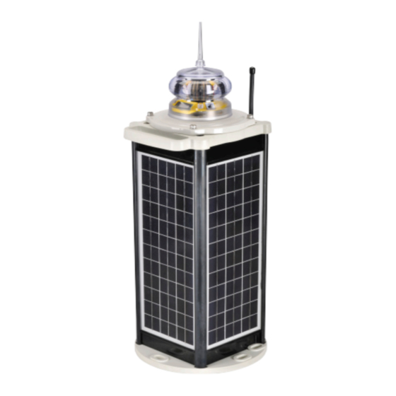
- Page 1 SL-C510 With AIS Compact 5-9NM Solar Marine Lantern INSTALLATION & SERVICE MANUAL V1-4...
- Page 2 Version No. Description Date Author Approved Manual Launch June 2019 J.Ohle / M.Nicholson M.Nicholson Update AIS Battery images August 2019 M.Dutka M.Nicholson Lantern Data Update July 2020 M.Dutka M.Nicholson Update to AIS programming procedure November 2020 M.Dutka M.Nicholson Grounding advice February 2021 M.Dutka M.Nicholsond...
-
Page 3: Table Of Contents
AIS Configuration - Message 21 and Message 6 ............Page 59 Appendix ..........................Page 68 Flash Codes ........................Page 69 Maintenance & Servicing ....................Page 75 Trouble Shooting ....................... Page 79 Sealite LED Light Warranty ..................... Page 79 Latest products and information available at www.sealite.com... -
Page 4: Introduction
As a commitment to producing the highest quality products for our customers, Sealite has been independently certified as complying with the requirements of ISO9001:2015 quality management system. Sealite lanterns comply with requirements of the US Coast Guard in 33 CFR part 66 for Private Aids to Navigation. -
Page 5: C510 With Ais Model
The SL-C510 with AIS is available with GPS Synchronisation as standard. Two (2) or more lights can be synchronised to flash in unison via an internal GPS module. The SL-C510 with AIS is backed by Sealite’s industry leading 3-year warranty. LED Optic... -
Page 6: Installation
For location suitability use the Sealite Online Solar Calculator and ensure ‘extra charge’ all year round. Note: The SL-C510-AIS must be grounded via the grounding post at the base of the chassis. Failure to do so will void your warranty. - Page 7 3. Carefully place the light head assembly back onto the chassis ensuring the O-ring is properly placed. 4. Replace the four (4) socket head screws. Sealite recommends that the light head be tightened onto the solar chassis base using a general purpose “grip tool”, similar in shape to a screwdriver, however with the appropriate hex key head fitted.
-
Page 8: Viewing Lantern Settings
Pad device is activated again. NOTE – The OLED display and Touch Pad components are designed to provide lantern settings/status readings only, the lantern programming can be achieved by one of the Sealite lantern programming methods, the information is available in this product manual. -
Page 9: Summary Of Lantern Status
Indicates the lantern current Flash Code. Flash Code:0F4 This information provides Sealite’s Flash Code in Hex decimal and the on/off flash duration. Please refer to the provided list of Flash Codes included in the appendix. Displays the lantern operating intensity in percentage. The SL-C510 can provide four different intensity levels in percentage or with a step size of 3.125% (or 1/32%) nautical... -
Page 10: Programming The Lantern
Programming the Lantern SealitePro Bluetooth Guide ® The SealitePro application is used to communicate with Sealite lighting products that have ® Bluetooth technology fitted. The Bluetooth control offers the following main functionality: • Lantern Information • Lantern Status • Solar Calculations •... -
Page 11: Accessing The Sealitepro ® App For The First Time
Download the SealitePro App from Google Play (search for ® “Sealite” in the store) on an Android Tablet or Smartphone or via the App store on an iOS tablet or phone. Open the App to prompt the Sealite Bluetooth control system. - Page 12 Identify Bluetooth Radio ID When “Identify” on the Tablet or phone is selected, the connected lantern will flash quickly (10 times). For iOS, identify is represented by a flash / burst icon. Set the Lantern Name 1. Press “Name” to change the lantern name. A user defined name, comprising up to 16 alpha- numeric characters (and -, $, # @) can be typed into the dialogue box.
-
Page 13: Sealitepro ® Password Reset Procedure
(“Bluetooth Authentication for iOS”). NOTE – If “User Authenticated” under “Authentication Level” or Bluetooth Authentication appears the limited time that allows to modify the PIN has expired. Therefore, start the process again at Step 1; Authenticated Latest products and information available at www.sealite.com... -
Page 14: Lantern Status
(d). If “No PIN Set” appears under Authentication Level, please press Change PIN; (e). Enter a New PIN and press “OK”. A prompt to confirm PIN will appear. Re-enter the same PIN and press “OK”. (f). One the procedure is complete, ensure the 4 socket head screws are replaced to secure the light head and solar chassis. -
Page 15: Solar Calculations
• Autonomy This function estimates the lantern autonomy based on the lantern settings and geolocation. • Option 1 Use the current GPS location to establish the lantern autonomy. Latest products and information available at www.sealite.com... - Page 16 • Option 2 An alternate method for setting the calculator is by using the “Solar calculator” function. Select your product from the option(s) available, then select “Simulation Geolocation”. Set Autonomy Location - Select a location globally to estimate the lantern autonomy if installed at that location The autonomy will be shown in amber or red if the configuration is not recommended.
-
Page 17: Programming Options
Once the Operating Mode is selected press “Set / Apply“ to confirm the change. As factory default the lantern is always set to Dusk till Dawn mode. Flash Code Sealite marine lanterns may be set to any of the 256 IALA recommended flash characters which are user-adjustable on site. SEALITE code reference is listed by the number of flashes. - Page 18 Sealite Flash Code table provided in the Appendix Section. 2. Code – Select the Flash Code from the Sealite Flash Code table provided in the Appendix section. Once the Flash Code is established press “Set / Apply” to confirm the change.
- Page 19 Custom – Create sequences of custom Flash Codes by nominating the on/off times. Once the Flash Code is established press “Set /Apply” to confirm the change. To add multiple flashing configurations, press “add” for each configuration. Latest products and information available at www.sealite.com...
- Page 20 Intensity The lantern intensity level can be set by either defining the operating range of the lantern (in nautical miles) or by entering the available percentage intensity level. When Schmidt Clausen is applied, the lantern will automatically adjust the intensity level based on the entered range and Flash Code setting.
- Page 21 This panel is used to set a Flash Code delay. The built-in GPS receiver and advanced software of the Sealite synchronised lanterns allow for the adoption of Sync Offset channel marking – a unique system that cascades the flash synchronisation of channel lanterns in a uni or bi-directional flash pattern. By default, this figure is set to zero.
- Page 22 GPS Mode The lanterns come fitted with a GPS module, and provide the user with the ability to install independently operating lanterns that all flash in Synchronisation. No additional power supplies, aerials or control systems are required and with its microprocessor-based system, the GPS is specifically designed to provide maximum reliability and performance over a wide range of environmental conditions.
-
Page 23: Manufacturing Data
Data” tab. From this drop-down tab the user will be able to verify the information that identifies the lantern’s internal electronic hardware and firmware versions. Moreover, the Lantern Printed Circuit Board Serial number is identified. Latest products and information available at www.sealite.com... - Page 24 Let’s try a practical example If Bluetooth connection is established, data about the lantern battery charge and load current will appear on the “Power Monitoring” tab. From this drop-down tab the user will be able to verify the amount of battery charge that the lantern was able to capture in the previous 24 hours. In addition, the information of load current through the system can be monitored.
- Page 25 Select “Perform Reset” to confirm the reset. Please Note – Applying the Factory Reset will also reset the Security Pin if one was set by the user. SL-C510 Latest products and information available at www.sealite.com...
-
Page 26: Sealitepro ® Troubleshooting
No. The lantern will operate without setting a Security PIN. How- start using the lantern? ever, it is highly recommended by Sealite for customers to set a unique PIN from the moment the lantern starts to operate. When I try to download SealitePro... - Page 27 1. Verify that a Bluetooth-equipped Sealite lantern is nearby and powered on. 2. Verify that no other mobile device is connected to the lantern via Bluetooth. Bluetooth supports only one connection at a time, therefore if another device is connected it must be disconnected before the lantern appears in a scan result.
-
Page 28: Optional Ir Remote Control
Optional IR Remote Control The IR programmer is used to communicate with Sealite lighting products that have an IR sensor fitted. The remote control is used for the following functions: • Flash Code: Read the current flash code, configure a new flash code. - Page 29 This sets the light intensity to 25%. Battery Status This function reads the battery status. The response from the light is High Voltage: 4 flashes, Good Voltage: 3 flashes, Low Voltage 2 flashes, Cutoff Voltage or below: 1 flash. Latest products and information available at www.sealite.com...
- Page 30 This key sets the ambient light threshold levels. The format is where ‘x’ is the desired setting from the table below. There are 5 programmable lux levels which are set together for the sunset and sunrise transitions. Sunset Sunrise Level (Dusk) (Dawn) * Default / Factory Preset...
- Page 31 Hibernation Mode. Power consumption is only improved by physically disconnecting the battery supply. Hibernation Mode is defined by a start date and end date that are programmed into the lantern via the IR Remote Control. Latest products and information available at www.sealite.com...
- Page 32 Using the IR Remote Control The lantern must be in Test Mode prior to pressing any of the following key sequences. However, the lantern will return to Normal Operation if it has not detected a valid key press for a period of 15 seconds.
- Page 33 By pressing the following key sequence the lantern will enter Storage Mode: The lantern will leave storage mode when exposed to daylight or if the power switch is turned OFF and ON again. Latest products and information available at www.sealite.com...
- Page 34 IR Controller Security PIN The IR Controller allows to create a four-digit numbers security access PIN, this will prevent accessing or modifying the SL-C510 settings. Once the Security PIN is set this it will lock the lantern immediately. In order to access the light settings, the Unlock PIN command needs to be used, this will allow access to the light settings for 30 minutes then the light will re-lock again.
-
Page 35: Gps Synchronisation
If the light turns on unsynchronised it will continually check for valid time data. Once valid data is found the light will automatically synchronise. Note: Lights will not synchronise if different flash codes are selected. Latest products and information available at www.sealite.com... -
Page 36: Lantern Status
The yellow status LED is used to indicate the operational status of the lantern. These indicator LED’s can be viewed at the base of the lens. All Sealite boards are fitted with two Indicator LED’s. Use the table below to help determine operational status. -
Page 37: Lantern Thermal Management
10.6 13.1 13.1 13.4 Max power at Thermal Limit (%) 40.6 40.6 40.6 40.6 40.6 Max power at Thermal Limit Multiplier* (W) Peak Intensity (cd) * See Thermal Limit Operation for full description. Latest products and information available at www.sealite.com... -
Page 38: Thermal Limit Operation
Thermal Limit Operation Automatically the lantern calculates the MULTIPLIER and compares it to the maximum power Thermal Limit. If the calculated value exceeds maximum power thermal limit, then the intensity is reduced to the highest intensity step to ensure that it is not exceeded. a) Power is a measure of the rate in which electrical energy is transferred within an electrical circuit and is measured in Watts (W). -
Page 39: Ais Programming
AIS messages sent from a shore station (known as VDL configuration). An extension of VDL configuration is ‘Chaining’ where configuration and query commands are passed along a ‘chain’ of AIS AtoN stations to a distant station beyond the range of direct communication with a shore station. Latest products and information available at www.sealite.com... - Page 40 AIS Glossary Term Definition Automatic Identification System AtoN Aid to Navigation BeiDou Not supported. Chinese satellite navigation system. Now expanded to BeiDou-3 and is expected to provide global services upon completion in 2020. BIIT Built In Integrity Test Destination Area Code FATDMA Default = 235 (UK &...
- Page 41 Single slot binary Transmitted and This message can be used for remote (over message received the air) configuration of the transceiver and configuration of a ‘chain’ of transceivers. Latest products and information available at www.sealite.com...
- Page 42 Configuration of the source for external equipment status information The SL-C510 with AIS AtoN supports VDL configuration and chaining. For further information please contact Sealite for support. Installing the proAtoN PC Software Tool The proAtoN should be installed from the CD supplied (or USB stick) with the transceiver. The steps to...
- Page 43 Message schedule tab Configuration of FATDMA or RATDMA message schedules. • Virtual AtoN tab Configuration of virtual and/or synthetic AtoN transmissions. • Status input tab Configuration of the source for AtoN status information Latest products and information available at www.sealite.com...
- Page 44 When connected to a transceiver a synchronisation status icon is displayed alongside the title of each tab. This icon indicates the current synchronisation status of the information displayed in that tab with the internal configuration of the transceiver. The synchronisation status icons are illustrated as: Synchronisation is achieved by either writing the configuration displayed in proAtoN to the transceiver (click the write configuration...
- Page 45 (AIS1 and AIS2) should be used. Transmitter Power Level The transmitter power level for the transceiver can be selected as 1W, 2W, 5W or 12.5W. The default value of 12.5W is appropriate for most scenarios. Latest products and information available at www.sealite.com...
- Page 46 AIS Message Schedule Configuration The layout of the message schedule tab is illustrated below: Default Messages An AIS AtoN position report is made using AIS message #21. This message occupies two AIS slots. The default configuration shown in proAtoN includes two message #21 schedule configurations. The first configuration, Index 1, is the primary position reporting schedule for the transceiver.
- Page 47 This is the interval in slots between transmissions on Channel 2. The interval can range from 0 to 3240000 slots, which equates to an interval of one day. Typically the interval is set to 13500 slots (6 minutes) on each channel which results in an overall interval of 3 minutes. Latest products and information available at www.sealite.com...
- Page 48 Example FATDMA Schedule A typical transmission schedule requires that the AIS AtoN transceiver transmits AIS message #21 every three minutes on alternating channels. The transmission schedule is presented diagrammatically in the following figure: This schedule can be configured using the following values: •...
- Page 49 Channel 2 every 6th minute, but offset by three minutes from Channel 1. This results in a transmission of message #21 every three minutes on alternating channels. The exact timings of the transmissions within the selected minute will vary as the transceiver selects available slots using RATDMA. Latest products and information available at www.sealite.com...
- Page 50 CAUTION It is not recommended to use this feature as it significantly drains the internal battery. Contact Sealite for additional advice. Virtual AIS AtoN Configuration Each virtual AtoN required must be separately enabled by checking the ‘Enable’ check box. The type of virtual AtoN can then be selected: •...
- Page 51 An addressed or broadcast text message can be transmitted when the transceiver determines that it is off position. This message is in addition to use of the alternate schedule for off position reporting (if the alternate schedule is enabled) and does not replace that function. Latest products and information available at www.sealite.com...
- Page 52 The layout of the alert messages configuration tab is illustrated in the following picture: BIIT Failure Actions This section allows configuration of the text message to be transmitted on detection of a Built In Integrity Test failure (BIIT failure). Such a failure may indicate a problem with the transceiver and it may be prudent to warn vessels not to rely on the information provided by the transceiver in this situation.
- Page 53 ‘Message schedule’ tab. • Message #14 index 2 must be configured if the message #14 action is selected • Message #12 index 3 must be configured if the message #12 action is selected Latest products and information available at www.sealite.com...
- Page 54 CAUTION It is not recommended to use this feature as it significantly drains the internal battery. Contact Sealite for additional advice. For each message type, the repeat function can be disabled - Off - or enabled to repeat received messages with a Repeat Indicator (RI) value equal to or less than 0, 1 or 2. The RI value states how many times the message has already been repeated where 0 means it was transmitted by the source.
- Page 55 ‘Log to File’ button. Certain sentence types can be filtered out of the output window by checking the relevant sentence type in the ‘Filters’ section of this tab. Latest products and information available at www.sealite.com...
- Page 56 Diagnostics Tab The Diagnostics tab provides system version and status information. This information may be required when requesting technical support for the product. AtoN Details • The connected AtoN Type is displayed as Type 1 or Type 3 • The application and boot loader software versions for the connected AtoN are displayed •...
- Page 57 The transceiver cannot enter standby mode if the current configuration has the message repeater function enabled. Exiting standby Information only on exit of standby mode. Entering standby for xx seconds Information only on entry to standby mode. Latest products and information available at www.sealite.com...
- Page 58 Active Alarm The transceiver incorporates BIIT (Built In Integrity Test) routines which continuously monitor key operating parameters. Should an integrity test fail, the failure will be indicated in the active alarms area. Alarm text Description / Resolution Tx Malfunction A transmitter malfunction has been detected. Antenna VSWR exceeds Contact your supplier.
-
Page 59: Ais Configuration - Message 21 And Message 6
AIS Configuration - Message 21 and Message 6 The process for configuring a SL-C510 with AIS to transmit Sealite Message 21 and Message 6 GLA. It is also applicable to a standalone SL-AIS-C1 or SL-AIS-C3 without sensor board option fitted and not connected to a lantern. - Page 60 Prior to commencing this procedure, a number of parameters are required to configure the AIS AtoN. This information maybe be provided to you in the form of: • “Sealite-Lantern-and-AIS-Setup-Requirements-RevE (2).DOCX” The details required varies according to whether it is a Type 1 or Type 3 AIS AtoN. • Configuration detail required for Type 1 For a type 1 AIS AtoN to operate, it relies on being assigned/allocated a specific timing slots typically assigned by a local AIS base station or RF spectrum management authority.
- Page 61 6. Use a 12VDC battery of at least 24Ah capacity to power a AIS AtoN or a DC 6A , 12VDC PSU as the peak currents when transmitting are at least 3.5A at 12VDC for about 40ms. A battery is better as most AC/DC power supplies will momentarily lose regulation and Latest products and information available at www.sealite.com...
- Page 62 briefly trip their internal over current protection with a fast rising, short period peak current draw. A battery will for short periods act as a large capacitor and support high peak current excess of the AtoN’s requirements. Keep the AIS AtoN power cable length to a maximum 3m. 8.
- Page 63 5. To connect to the transceiver, select the ‘ A IS AtoN Port’ option from the drop down and click the ‘Connect’ button as shown in Figure 3. 6. With reference to your configuration table enter in the highlighted sections and then press the Message Schedule Tab. Figure 3 Latest products and information available at www.sealite.com...
- Page 64 7. Click on the Message schedule tab and input values highlighted. These values will come from the data collected at the beginning of this procedure. Figure 4 Note: If Message 6 is required, then click on the button and new Message schedule will appear and then follow the next step.
- Page 65 24. Ensure Regional Number is 228 (Light OFF) as shown in Figure 8 25. Create Alarm condition by setting input voltage to 11VDC. 26. Message 21 ALARM as shown in Figure 9. 27. Make sure Regional Number is 231 (ALARM) as shown in Figure 9. Latest products and information available at www.sealite.com...
- Page 66 37. Adjust input voltage back to 12.6VDC and turn the Light ON. 38. Sealite Message Light ON format as shown in Figure 13. 39. Make sure ‘Night’ message is displayed and Status Flags is (0x28) as shown in Figure 13.
- Page 67 SL-C510-AIS Compact 5-9NM Solar Marine Lantern 44. Sealite Message ‘Flat Battery’ as shown in Figure 15. 45. Make sure ALARM message is displayed as shown in Figure 15. The table below lists all the codes for type of AtoN defined by IALA:...
-
Page 68: Appendix
Appendix Flash Codes The Sealite SL-C510 may be set to any of 256 IALA recommended flash settings which are user adjustable onsite without the need for external devices. SEALITE code reference is listed by number of flashes ® For the latest version of this document visit www.sealite.com, or email info@sealite.com... - Page 69 FL 5 S FL 5 S ISO 2 S FL 2.5 S FL 5 S FL 5 S FL 2.5 S FL 2.5 S FL 5 S FL 5 S FL 3 S Latest products and information available at www.sealite.com...
- Page 70 CODE IR Controller FLASH CODE CODE IR Controller FLASH CODE ISO 5 S OC 8 S LFL 5 S LFL 8 S OC 5 S FL 9 S OC 5 S FL 9 S OC 5 S OC 9 S FL 6 S FL 10 S FL 6 S...
- Page 71 FL (2) 10 S FL (2) 10 S Q (2) 10 S FL (2) 12 S 10.2 FL (2) 12 S 10.0 FL (2) 12 S FL (2) 15 S 11.0 FL (2) 15 S 11.0 Latest products and information available at www.sealite.com...
- Page 72 HEX CODE IR Controller FLASH CODE Q (3) 5 S VQ (3) 5 S VQ (3) 5 S VQ (3) 5 S FL (3) 5 S FL (3) 6 S FL (2+1) 6 S HEX CODE IR Controller FLASH CODE Q (3) 6 S FL (3) 8 S FL (3) 8 S...
- Page 73 FL (5) 16 S FL (5) 20 S 15.5 FL (5) 20 S 11.2 FL (5) 20 S 11.0 CODE Controller FLASH CODE Q (6) 10 S FL (6) 15 S FL (6) 15 S Latest products and information available at www.sealite.com...
- Page 74 CODE Controller FLASH CODE VQ (6) + LFL 10 S VQ (6) + LFL 10 S Q (6) + LFL 15 S Q (6) + LFL 15 S Q (6) + LFL 15 S FL (6 + 1) 15 S 0.35 0.65 0.35 0.65 0.35 0.65 0.35 0.65 0.35 0.65 0.35 0.65 1.05 7.95 FL (6) + LFL 15 S...
-
Page 75: Maintenance & Servicing
Designed to be almost maintenance-free, the SL-C510 with AIS requires minimal attention, though the following maintenance and servicing information is provided to help ensure the life of your Sealite product. Cleaning Solar Panels- Occasional cleaning of the solar panels may be required. Using a cloth and warm soapy water, wipe off any foreign matter before rinsing the panels with fresh water. - Page 76 Applying a higher Torque setting is not recommended and may void warranty. If in doubt, please contact your local Sealite representative. 14. To test, place dark cover (towel or jacket) on top of light to activate sensor, light will come on.
- Page 77 Sealite cannot guarantee the chassis will remain waterproof, if service is not performed by Sealite staff. To test for any leaks remove the gore vent and pressurise the assembled light to 1.5psi. Latest products and information available at www.sealite.com...
- Page 78 The replacement of a solar panel should only be performed by a confident technician. Sealite cannot guarantee the chassis will remain waterproof, if service is not performed by Sealite staff. To test for any leaks remove the gore vent and pressurise the assembled Light to 1.5psi.
-
Page 79: Trouble Shooting
• Expose the lantern to direct sunlight and monitor operation for several entire night. days. • Sealite products typically require 1.5hours of direct sunlight per day to retain full autonomy. From a discharged state, the lantern may require several days of operational conditions to ‘cycle’ up to full autonomy;... - Page 80 We believe technology improves navigation sealite.com info@sealite.com Sealite Pty Ltd Sealite Asia Pte Ltd Sealite United Kingdom Ltd Sealite USA LLC Australia Singapore +61 (0)3 5977 6128 +65 6908 2917 +44 (0) 1502 588026 +1 (603) 737 1311...
Need help?
Do you have a question about the SL-C510-AIS and is the answer not in the manual?
Questions and answers