Table of Contents
Advertisement
Quick Links
Advertisement
Table of Contents
Troubleshooting

Related Manuals for Sealite SL-C510


Summary of Contents for Sealite SL-C510
- Page 1 SL-C510 Compact 5-9NM Solar Marine Lantern INSTALLATION & SERVICE MANUAL V1.0...
- Page 2 Version No. Description Date Approved Manual Launch March 2019 M.Nicholson...
-
Page 3: Table Of Contents
Lantern Data..............................Page 50 Thermal Limit Operation........................... Page 51 Appendix.................................. Page 52 Flash Codes..............................Page 52 Maintenance & Servicing..........................Page 59 Trouble Shooting..............................Page 62 Sealite LED Light Warranty......................... Page 62 Notes.................................... Page 63 Latest products and information available at www.sealite.com... -
Page 4: Introduction
As a commitment to producing the highest quality products for our customers, Sealite has been independently certifi ed as complying with the requirements of ISO9001:2015 quality management system. Sealite lanterns comply with requirements of the US Coast Guard in 33 CFR part 66 for Private Aids to Navigation. -
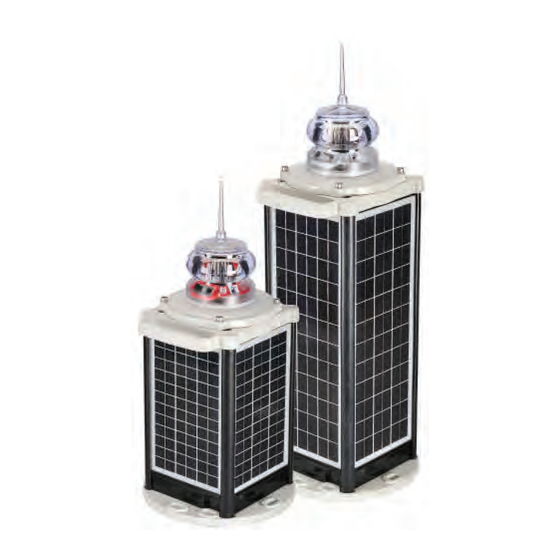
Page 5: Sl-C510 Model
50 metres. An in-built solar calculator confi rms the lanterns ability to operate at the set location, ensuring optimal operating performance. The SL-C510 is available with GPS Synchronisation as standard. Two (2) or more lights can be synchronised to fl ash in unison via an internal GPS module. - Page 6 These components are securely packaged within protective wrap, in a carton and shipped to you. Please check that ALL of these components are included with your order and contact your Sealite representative as soon as possible if anything is missing.
-
Page 7: Installation
Intensity settings need to be set via the SealitePro App or the Sealite IR Controller. Remove the four socket-head screws on the top of the lens assembly and lift the SL-C510 (light head) assembly from the solar chassis. 2. Join the 4-Pin connector together to join the battery and the solar panels to the light head. The battery is disconnected to reduce discharge during transportation and for long term storage. - Page 8 SL-C510 Compact Chassis 120° Slot 12.6 x 21.75 6 Locations SL-C510 Extended Chassis 120° Slot 12.6 x 21.75 6 Locations...
-
Page 9: Viewing Lantern Settings
Compact 5-9NM Solar Marine Lantern Viewing Lantern Settings The SL-C510 models are equipped with a very low power consumption OLED display, providing a quick and easy lantern status and diagnostic checks by maintenance staff. To activate the OLED display simply touch the indicated location. Once activated, the OLED will display in sequence the following information: •... -
Page 10: Summary Of Lantern Status
Indicates the lantern current Flash Code. Flash Code:0F4 This information provides Sealite’s Flash Code in Hex decimal and the on/off fl ash duration. Please refer to the provided list of Flash Codes included in the appendix. Displays the lantern operating intensity in percentage. The SL-C510 can provide four different intensity levels in percentage or with a step size of 3.125% (or 1/32%) nautical... -
Page 11: Programming The Lantern
Guide ® ® The SealitePro application is used to communicate with Sealite lighting products that have Bluetooth technology fi tted. To note, only one device may be connected at any one time. ® The Bluetooth control offers the following main functionality: •... -
Page 12: Sealitepro ® Bluetooth ® Controller Functions
® Bluetooth Controller Functions ® The Sealite SL-C510 Bluetooth ® Control System accessible via the SealitePro App is divided into seven simple sections as outlined below and displayed on the App home screen; • Lantern Identifi cation • Lantern Type •... - Page 13 • Charge Current • Charge Current – Last Hour • Charge Current - Yesterday • Hardware • Board Serial Number • Manufacture Date • Software Version • Test LED • Perform Factory Reset Latest products and information available at www.sealite.com...
-
Page 14: Accessing The Sealitepro ® App For The Fi Rst Time
® store) on an Android Tablet or Smartphone or via the App store on an iOS tablet or phone. Open the App to prompt the Sealite Bluetooth control system. Start Menu • Connect via Bluetooth - connect to a lantern. - Page 15 (and -, $, # @) can be typed into the dialogue box. It is recommended that the lantern be programmed with a unique name. 2. Press apply and then Set to confi rm. Latest products and information available at www.sealite.com...
- Page 16 Create Security Access PIN The factory default does not set the lantern with a Security PIN. 1. To set a PIN, select “Authentication Level” (“Bluetooth Authentication for iOS”) then enter a New PIN and press “OK”. A confi rmation of the PIN will be prompted. 2.
-
Page 17: Sealitepro ® Password Reset Procedure
In the event where the password set is unknown the procedure below should be followed: Step 1 – Disconnect the power supply from the light head: (a). Remove the four socket-head screws on the top of the lens assembly and lift the SL-C510 (lantern head) assembly from the solar chassis. - Page 18 (c). Expand the “Lantern Information” drop down menu then press select “Authentication Level” (“Bluetooth Authentication for iOS”). NOTE – If “User Authenticated” under “Authentication Level” or Bluetooth Authentication appears the limited time that allows to modify the PIN has expired. Therefore, start the process again at Step 1;...
-
Page 19: Lantern Status
Displays the battery health status, the current light sensor state and if the GPS is enabled, synchronised or off station. Any warning states will cause the status to be shown in amber or red. • Lantern Geolocation Displays the lantern coordinates and allows the location to be plotted on a map. Latest products and information available at www.sealite.com... -
Page 20: Solar Calculations
This function estimates the lantern autonomy based on the lanterns current settings and geolocation. • Solar Calculator Options The SL-C510 has options to be fi tted with Satcoms and GSM modules to allow multiple lanterns ® synchronisation and monitoring. The SealitePro App offers the user the option to modify the GPS and GSM by enabling or disabling the operation. - Page 21 Use the current GPS location to establish the lantern autonomy. • Option 2 An alternate method for setting the calculator is by using the “Solar calculator” function. Select your product from the option(s) available, then select “Simulation Geolocation”. 1097 candela Latest products and information available at www.sealite.com...
- Page 22 Set Autonomy Location - Select a location globally to estimate the lantern autonomy if installed at that location The autonomy will be shown in amber or red if the confi guration is not recommended.
-
Page 23: Programming Options
Dusk till Dawn – The daylight sensor is monitored, and the lantern will only operate at night time. Once the Operating Mode is selected press “Set / Apply” to confi rm the change. As factory default the lantern is always set to Dusk till Dawn mode. Latest products and information available at www.sealite.com... - Page 24 Flash Code Sealite marine lanterns may be set to any of the 256 IALA recommended fl ash characters which are user-adjustable on site. ® SEALITE code reference is listed by the number of fl ashes. For the latest version of this document visit www.sealite.com...
- Page 25 SL-C510 Compact 5-9NM Solar Marine Lantern Code – Select the Flash Code from the Sealite Flash Code table provided in the Appendix section. Once the Flash Code is established press “Set / Apply” to confi rm the change. Please Note – The number of fl ashing combinations are limited. For more information please check the Sealite Flash Code table.
- Page 27 NOTE: This does not apply for changing Flash Code - the user must re-set the intensity. Select Intensity – Choose one of four intensity values - 25%, 50%, 75% or 100%. Select Intensity – Choose one of Nautical Miles ranges available. Latest products and information available at www.sealite.com...
- Page 28 NOTE – If an intensity level is selected that is beyond the specifi cation of the lantern, the entered fi gure will be displayed in red, with the lantern automatically confi guring to the maximum possible of 100%. In addition, once the intensity is selected the winter autonomy will be recalculated.
- Page 29 This panel is used to set a Flash Code delay. The built-in GPS receiver and advanced software of the Sealite synchronised lanterns allow for the adoption of Sync Offset channel marking – a unique system that cascades the fl ash synchronisation of channel lanterns in a uni or bi- directional fl...
- Page 30 GPS Mode The lanterns come fi tted with a GPS module, and provide the user with the ability to install independently operating lanterns that all fl ash in Synchronisation. No additional power supplies, aerials or control systems are required and with its microprocessor-based system, the GPS is specifi...
- Page 31 Hibernation Mode can be set by programming a start date and end date via the SealitePro enable the Hibernation Mode, tick on the top left box then select the Hibernation start date and Reawaken date. Press “Set / Apply” to confi rm the settings. Latest products and information available at www.sealite.com...
-
Page 32: Manufacturing Data
Data” tab. From this drop-down tab the user will be able to verify the information that identifi es the lantern’s internal electronic hardware and fi rmware versions. Moreover, the Lantern Printed Circuit Board Serial number is identifi ed. SL-C510 Marine... - Page 33 • Email Lantern Data: This function allows to send the lantern confi guration and status via email. • Email Lantern Data: This function allows to send the lantern confi guration and status via email. Latest products and information available at www.sealite.com...
- Page 34 ® • Set Default Email* Note Android only This option allows to search for an existing contact on the device to use as the default recipient of confi guration and status emails.
- Page 35 Select “Perform Reset” to confi rm the reset. Please Note – Applying the Factory Reset will also reset the Security Pin if one was set by the user. SL-C510 SL-C510 Marine Latest products and information available at www.sealite.com...
-
Page 36: Sealitepro Troubleshooting
Do I need to create a PIN when I fi rst No. The lantern will operate without setting a Security PIN. start using the lantern? However, it is highly recommended by Sealite for customers to set a unique PIN from the moment the lantern starts to operate. ®... - Page 37 1. Verify that a Bluetooth-equipped Sealite lantern is nearby and powered on. 2. Verify that no other mobile device is connected to the lantern via Bluetooth. Bluetooth supports only one connection at a time, therefore if another device is connected it must be disconnected before the lantern appears in a scan result.
-
Page 38: Optional Ir Remote Control
Optional IR Remote Control The IR programmer is used to communicate with Sealite lighting products that have an IR sensor fi tted. The remote control is used for the following functions: • Flash Code: Read the current fl ash code, confi gure a new fl ash code. - Page 39 Levels are in the range of 1 to 5. Flash Code This key sets the Flash Code on the light. Example Key sequence: This sets the Flash Code to value 123. The light responds by fl ashing the Flash Code value. Latest products and information available at www.sealite.com...
- Page 40 Flash Code Numbers The lamp fl ashes numbers as follows: Hundreds, Tens, Ones. A value of 125 will be fl ashed as: 1 fl ash, followed by a delay, 2 fl ashes, followed by a delay, 5 fl ashes. The fl ash for number 0 is one long fl ash. For example if the current Flash Code is set to 51 via the AB switches, the lamp will fl...
- Page 41 This sets the ambient light level to be lower than the default 100 lux. The light will turn on when its surroundings are darker. The light responds by acknowledgement with a long fl ash. Latest products and information available at www.sealite.com...
- Page 42 Error / Acknowledge Indication If the key sequence is invalid, or an out of bounds value is attempted to be set, the light fl ashes 5 times for 1 second. (The command then needs to be sent from the start.) Example key sequence: (Set the intensity level to 5 –...
- Page 43 Normal Operation if it has not detected a valid key press for a period of 15 seconds. When the lantern exits from Test Mode it will either enter Dusk to Dawn mode, Hibernation Mode, or Storage Mode, if enabled. Latest products and information available at www.sealite.com...
- Page 44 Store Hibernation Mode Date Range The following details the key press sequence that defi nes the start and end dates of Hibernation Mode: where ddmm is the numerical representation of the month (01=January, 08=August) of the start date, DDMM is the numerical representation of the end date. E.g 9th of December is represented by the number sequence 0912.
- Page 45 By pressing the following key sequence the lantern will enter Storage Mode: The lantern will leave storage mode when exposed to daylight or if the power switch is turned OFF and ON again. Latest products and information available at www.sealite.com...
- Page 46 IR Controller Security PIN The IR Controller allows to create a four-digit numbers security access PIN, this will prevent accessing or modifying the SL-510 settings. Once the Security PIN is set this it will lock the lantern immediately. In order to access the light settings, the Unlock PIN command needs to be used, this will allow access to the light settings for 30 minutes then the light will re-lock again.
-
Page 47: Optional Gps Synchronisation
Compact 5-9NM Solar Marine Lantern GPS Synchronisation The SL-C510 lanterns are fi tted with GPS and provide the user with the ability to install independently operating lanterns that all fl ash in synchronisation. No additional power supplies, aerials or control systems are required, and with its microprocessor- based system, the GPS option is specifi... -
Page 48: Optional Gsm Monitoring & Control System
Optional GSM Monitoring & Control System The SL-C510 may also be fi tted with GSM Cell-Phone Monitoring and Control – enabling users to access real-time diagnostics data and change lantern settings via cell-phone. The system can also be confi gured to send out alarm SMS text messages to designated cellular telephone numbers. The user can also have alarms and reports sent to designated email addresses. -
Page 49: Lantern Status
The yellow status LED is used to indicate the operational status of the lantern. These indicator LED’s can be viewed at the base of the lens. All Sealite boards are fi tted with two Indicator LED’s. Use the table below to help determine operational status. -
Page 50: Lantern Thermal Management
The Thermal Management system does so by multiplying the fl ash character duty cycle with the lantern intensity and compares this fi gure to the Thermal Limit. All the SL-C510 models have the same Thermal limits for all colours. If the fi gure (called the “multiplier”) is greater than the Thermal Limit the intensity is then adjusted to ensure the Thermal Limit is not exceeded. -
Page 51: Thermal Limit Operation
Where the: MULTIPLIER (%) = Flash Character duty cycle (%) x Intensity level (%) d) The SL-C510 lantern intensity setting are available in 32 steps from 0% to 100% with a step size of 3.125% (or 1/32%) Latest products and information available at www.sealite.com... -
Page 52: Appendix
Appendix Flash Codes The Sealite SL-C510 may be set to any of 256 IALA recommended fl ash settings which are user- adjustable onsite. SEALITE ® code reference is listed by number of fl ashes For the latest version of this document visit www.sealite.com, or email info@sealite.com... - Page 53 FL 2 S FL 5 S ISO 2 S FL 2.5 S FL 5 S FL 2.5 S FL 5 S FL 2.5 S FL 5 S FL 3 S FL 5 S Latest products and information available at www.sealite.com...
- Page 54 CODE IR Controller FLASH CODE CODE IR Controller FLASH CODE ISO 5 S OC 8 S LFL 5 S LFL 8 S OC 5 S FL 9 S OC 5 S FL 9 S OC 5 S OC 9 S FL 6 S FL 10 S FL 6 S...
- Page 55 FL (2) 12 S 10.0 FL (2) 12 S FL (2) 15 S 11.0 FL (2) 15 S 11.0 Q (2) 15 S 13.8 FL (2) 20 S 15.0 FL (2) 25 S 22.0 Latest products and information available at www.sealite.com...
- Page 56 HEX CODE IR Controller FLASH CODE Q (3) 5 S VQ (3) 5 S VQ (3) 5 S VQ (3) 5 S FL (3) 5 S FL (3) 6 S FL (2+1) 6 S HEX CODE IR Controller FLASH CODE Q (3) 6 S FL (3) 8 S FL (3) 8 S...
- Page 57 FL (5) 16 S FL (5) 20 S 15.5 FL (5) 20 S 11.2 FL (5) 20 S 11.0 CODE Controller FLASH CODE Q (6) 10 S FL (6) 15 S FL (6) 15 S Latest products and information available at www.sealite.com...
- Page 58 CODE Controller FLASH CODE VQ (6) + LFL 10 S VQ (6) + LFL 10 S Q (6) + LFL 15 S Q (6) + LFL 15 S Q (6) + LFL 15 S FL (6 + 1) 15 S 0.35 0.65 0.35 0.65 0.35 0.65 0.35 0.65 0.35 0.65 0.35 0.65 1.05 7.95 FL (6) + LFL 15 S...
-
Page 59: Maintenance & Servicing
The O-ring should be a rubber texture to ensure a complete and even seal. Replacing the Battery The SL-C510 have an internal battery compartment, which provides the user with the ability to change the battery after years of operation. Contact Sealite should a replacement battery required. - Page 60 Long Term Battery Storage If the SL-C510 is to be placed in storage for an extended period please follow the below information. The sealed lead acid batteries inside the lights must always be stored in a fully charged state. Always make sure to disconnect the light head from the solar unit.
- Page 61 14. Ensure the top O-ring is sitting correctly into the top casting. Refi t the light head and tighten the M6 x 20 socket head cap screws with the 4 x M6 nylon washers evenly. DO NOT OVERTIGHTEN. Latest products and information available at www.sealite.com...
-
Page 62: Trouble Shooting
• Expose the lantern to direct sunlight and monitor operation for several days. the entire night. • Sealite products typically require 1.5hours of direct sunlight per day to retain full autonomy. From a discharged state, the lantern may require several days of operational conditions to ‘cycle’... -
Page 63: Notes
SL-C510 Compact 5-9NM Solar Marine Lantern Notes Latest products and information available at www.sealite.com...
Need help?
Do you have a question about the SL-C510 and is the answer not in the manual?
Questions and answers