
Related Manuals for Sealite SL-125 Series


Summary of Contents for Sealite SL-125 Series
- Page 1 SL-125 Series & SL-125 Complete 5-9NM+ LED Marine Lantern Installation & Service Manual Version 4.6...
- Page 2 SL-125 Series 5-9NM+ LED Marine Lantern Bird deterrent spike LED lens and Sealite’s Automatic night 360o Omnidirectional activation LED Reflector (US Pat. No. 6,667,582. AU Pat. No. 778,918) Lens and base moulded from UV-stabilised LEXAN® polycarbonate (IP68 rating) Large industry standard...
-
Page 3: Table Of Contents
SL-125 Series 5-9NM+ LED Marine Lantern Table of Contents Introduction ..................... Page 4 Operating Principle ..................Page 4 Technology ...................... Page 4 SL-125 & SL-125-C Models ................Page 5 SL-125 Series..................Page 6 SL-125 Complete Available Configurations ..........Page 8 SL-125 Type 1 Complete ................ Page 9 SL-125 Type 2 Complete................ -
Page 4: Introduction
SL-125 Series 5-9NM+ LED Marine Lantern Introduction Congratulations! By choosing to purchase a Sealite lantern you have become the owner of one of the most advanced LED marine lanterns in the world. Sealite Pty Ltd has been manufacturing lanterns for over 25 years, and particular care has been taken to ensure your lantern gives years of service. As a commitment to producing the highest quality products for our customers, Sealite has been independently certified as complying with the requirements of ISO9001:2008 quality management system. Sealite lanterns comply with requirements of the US Coast Guard in 33 CFR part 66 for Private Aids To Navigation. By taking a few moments to browse through this booklet, you will become familiar with the versatility of your lantern, and be able to maximise its operating function. -
Page 5: 125 & Sl-125-C Models
(see Specifications table below). Each LED tier utilises the Sealite omnidirectional LED Reflector (US Pat. No. 6,667,582. AU Pat. No. 778, 918) to increase the intensity and uniformity of the horizontal output. In particular, the SL-125 4-tier model utilises a unique heat-dissipating domed lens to achieve maximum LED intensity output over a wider range of environmental conditions. -
Page 6: 125 Series
ISO9001:2008 Waterproof IP68 Intellectual Property Patents US Pat. No. 6,667,582. AU Pat. No. 778,918 Trademarks SEALITE® is a registered trademark of Sealite Pty Ltd Warranty * 3 years Options Available • GPS Synchronisation • Hard-wire Synchronisation • AIS Remote Monitoring •... - Page 7 SL-125 Series 5-9NM+ LED Marine Lantern Figure 1.1. Figure 1.2. SL-125-1 SL-125-2 & SL-125-3 Figure 1.3. Figure 1.4. SL-125-4 Base (all models) Latest products and information available at www.sealite.com...
-
Page 8: 125 Complete Available Configurations
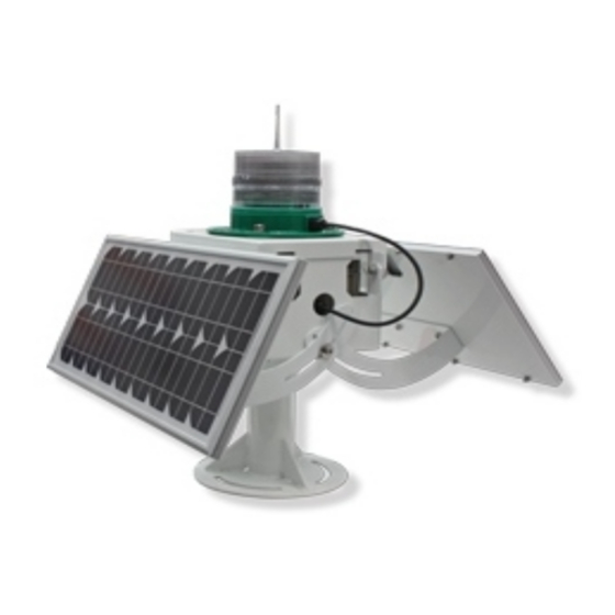
SL-125 Series 5-9NM+ LED Marine Lantern SL-125 Complete Available Configurations The SL-125 models outlined in Table 1.1 are available in a range of complete lantern assemblies. 1x (fixed installations) or 2x (buoy installations) 20watt solar modules may be fitted to the lantern as standard to provide a complete solution for visual navigation requirements. The lantern may also be equipped with up to 2x 40watt solar modules to power longer-range require- ments or ancillary equipment. Table 1.2. SL-125-C Type 1 Complete Lantern Assemblies Model Description SL-125-1/C-1 SL-125 1-Tier. Complete Lantern Assembly. Single 20w Solar Module. SL-125-1/C-2 SL-125 1-Tier. Complete Lantern Assembly. Dual 20w Solar Module. SL-125-2/C-1 SL-125 2-Tier. Complete Lantern Assembly. Single 20w Solar Module. SL-125-2/C-2 SL-125 2-Tier. Complete Lantern Assembly. Dual 20w Solar Module. Table 1.3. SL-125-C Type 2 Complete Lantern Assemblies... -
Page 9: 125 Type 1 Complete
IP68 light head. IP66 battery compartment Intellectual Property Patents US Pat. No. 6,667,582. AU Pat. No. 778,918 Trademarks SEALITE® is a registered trademark of Sealite Pty Ltd Warranty * 3 years Options Available • Single or dual solar module(s) • GPS Synchronisation •... -
Page 10: 125 Type 2 Complete
IP68 light head. IP66 battery compartment Intellectual Property Patents US Pat. No. 6,667,582. AU Pat. No. 778,918 Trademarks SEALITE® is a registered trademark of Sealite Pty Ltd Warranty * 3 years Options Available • SL-155 Series Lantern • Single or dual solar module(s) •... - Page 11 SL-125 Series 5-9NM+ LED Marine Lantern Figure 2.1. SL-125-1/C-1 Figure 2.2. SL-125-1/C-1.T2 Latest products and information available at www.sealite.com...
-
Page 12: Optional Configurations
SL-125 Series 5-9NM+ LED Marine Lantern Optional Configurations RF Synchronisation (SL-125-CS) The SL-125 may be fitted with optional comm sync RF module for short range flash synchronisation - ideal for marina entrances and aquaculture applications. GPS Synchronisation (SL-125-GPS) For flash synchronisation of lanterns installed over longer ranges, a GPS module may be fitted. When lanterns flash in synchronisation they can be clearly distinguished from other navaids and confusing background lighting - ideal for rivers and channel marking. GSM Monitoring & Control (SL-125-GSM) and AIS Integration (SL-125-AIS) The SL-125 lantern series may also be fitted with GSM remote monitoring and control capabilities - enabling users to access real-time diagnostics data and change lantern settings via cell-phone. AIS integration enables remote monitoring of the SL-125 lantern as well as crucial Message 21 information to be broadcast to mariners within the region. -
Page 13: Installation
SL-125 Series 5-9NM+ LED Marine Lantern Installation Settings of SL-125 & SL-125-C Models Before installing the light, intensity and flash settings must be set. 1. Remove the bolt/lock securing the battery box lid, and open unit (SL-125-C ONLY). 2. Remove the bung from the base of the SL-125 light. 3. The power and range settings of the lantern are adjusted by setting the DIP switches inside the lantern. Your lantern is normally set to maximum range (see ‘Selecting Intensity/Power Setting’ section of this manual). 4. Set rotary switches to the required flash code (see ‘Selecting a Flash Code’ section of this manual). 5. Replace bung. 6. A sealed vent on the base allows air transfer without moisture intake, and should not be disturbed. Note: Lantern is activated by connecting positive and negative battery wires (and solar module wires for SL-125-C). -
Page 14: Selecting An Intensity/Power Setting
SL-125 Series 5-9NM+ LED Marine Lantern Selecting an Intensity/Power Setting Intensity/power settings on Sealite lanterns operate via DIP switches, located near the rotary switches on the flasher unit. The intensity/power settings may be used to reduce the power consumption and intensity of the lantern. Setting the lantern to 25% intensity will reduce the power consumption to 25% of the normal 100% setting and the range by 20% - 40% depending on the maximum intensity. Refer to Sealite power calculator to confirm reduced range. This setting may be used to adjust the current draw of the light to local sunlight conditions. The following diagrams indicate intensity/power settings:- 100% Selecting a Flash Code - Rotary Switches A & B All lanterns have 2 rotary switches marked A and B on the flasher unit. Turning the small arrows to the appropriate number or letter will set the code. The unit will respond within 30 seconds to activate a new flash code. A comprehensive list of available flash codes is listed on in the ‘Flash Codes’ section of this manual. Example: SWITCH FLASH CODE FL 3 S Latest products and information available at www.sealite.com... -
Page 15: Ir Controller Functions
SL-125 Series 5-9NM+ LED Marine Lantern Optional IR Remote Control The IR remote is used to communicate with Sealite lighting products that have an IR sensor fitted. The remote control is used for the following functions: Test / Con gure • Flash Code: read the current flash code, configure a new flash code. • Lamp Intensity: read the current lamp intensity, configure a new intensity level. • Ambient Light Thresholds: read the current light thresholds, configure new ambient light thresholds. • Perform a battery health check. On receiving a valid key signal from the IR Remote, the light will flash once. The Read user should wait until the light responds to each keypress before pressing another key. If there is no response to the keypress after 3 seconds, it has not been Flash Code Intensity Battery Status detected by the light and the key can be pressed again. -
Page 16: Test Mode / Configure
SL-125 Series 5-9NM+ LED Marine Lantern IR Controller Functions Test Mode / Configure Pressing the T/C button for upto 5 seconds places the light in Test Mode. The light will flash once in response to the T/C button being pressed and then turn off. Normal Operation The light will return to normal operation once it has not detected a valid key press for 30 seconds. The light will flash once to indicate it is returning to normal operation. Read Pressing the Read followed by one of the configuration keys shall cause the light to flash the configured value. Example Key Sequences: The light flashes the ‘IR Remote’ number belonging to the currently set Flash Code. Refer to the Flash Code tables to match the ‘IR Remote’ flash number to the Flash Code. The light flashes the current intensity setting: 1 flash for 25%, 2 for 50%, 3 for 75% and 4 for 100%. The light flashes the current battery status. The light flashes the sunset level in Lux, followed by a 2 second gap, followed by the sunrise level. Levels are in the range of 1 to 9. -
Page 17: Flash Code
SL-125 Series 5-9NM+ LED Marine Lantern Flash Code This key sets the flash code on the light. Example Key sequence: This sets the flash code to value 123. The light responds by flashing the flash code value. Flash Code Numbers The lamp flashes numbers as follows: Hundreds, Tens, Ones. A value of 125 will be flashed as: 1 flash, followed by a delay, 2 flashes, followed by a delay, 5 flashes. The flash for number 0 is one long flash. For example if the current Flash Code is set to 51 via the AB switches, the lamp will flash number 081. For a flash code set to 01, the lamp will flash 001. Intensity This function sets the light intensity. Valid intensity values are 1 for 25%, 2 for 50%, 3 for 75% and 4 for 100%. Example Key sequence: This sets the light intensity to 25%. Battery Status This function reads the battery status. The response from the light is High Voltage: 4 flashes, Good Voltage: 3 flashes, Low Voltage 2 flashes, Cutoff Voltage or below: 1 flash. -
Page 18: Lux
SL-125 Series 5-9NM+ LED Marine Lantern Operational Mode Sets the Lanterns Operation mode: • Dusk to Dawn , • Always On, • Standby Dusk to Dawn Mode: at Dusk the light sensors will turn on the light and then synchronise to every other light with the same selected flash code. Always On: the light sensor is disabled and the light is turned on and then synchronised to every other light with the same selected flash code. Standby Mode: manually forces the lantern to turn off, disables the GPS but with access to daylight it will still charge the battery pack. Read Operation Mode Set Operation Mode to Always on Set Operation Mode to Standby Mode Set Operation Mode to Dusk to dawn This key sets the ambient light threshold levels. -
Page 19: Error / Acknowledge Indication
SL-125 Series 5-9NM+ LED Marine Lantern Error / Acknowledge Indication If the key sequence is invalid, or an out of bounds value is attempted to be set, the light flashes 5 times for 1 second. (The command then needs to be sent from the start.) Example key sequence: (Set the intensity level to 5 – undefined.) The light flashes 5 times for 1 second. When a key sequence has been entered successfully the light will respond acknowledgement with a long 1 second flash. Configuration Settings The intensity and flash codes can be changed using the switches on the lamp circuit board or with the IR Remote Control. The lamp intensity and flash code settings are set to the last detected change, carried out with the IR Remote Control or by changing the switch positions. Example #1: If the intensity is set at 100% with the intensity switches, and is then set to 50% using the IR Remote Control, the intensity setting will change to 50%. If the intensity is then set to 75% using the switches, the new intensity value will be 75%. -
Page 20: Hibernation Mode (Advanced Users)
SL-125 Series 5-9NM+ LED Marine Lantern Hibernation Mode (Advanced users) For situations where the lantern is put into storage for a known period, the IR Remote control can be used to configure the lantern into Hibernation Mode for a user programmable date range. Hibernation Mode maximises conservation of the battery power by disabling the light (will not activate at night) and shutting off the GPS receiver to rely on the internal clock for date checking. The IR sensor is still monitored in hibernation mode. Power consumption is only bettered by physically disconnecting the battery supply. Hibernation Mode is defined by a start date and end date that are programmed into the lantern via the IR Remote Control. Using the IR Remote Control The lantern must be in Test Mode prior to pressing any of the following key sequences. However, the lantern will return to Normal Operation if it has not detected a valid key press for a period of 15 seconds. When the lantern exits from Test Mode it will either enter Dusk to Dawn mode, Hibernation mode, or Storage Mode, if enabled. Store Hibernation Mode Date Range The following details the key press sequence that defines the start and end dates of Hibernation Mode: where ddmm is the numerical representation of the month (01=January, 08=August) of the start date, and DDMM is the numerical representation of the end date. - Page 21 SL-125 Series 5-9NM+ LED Marine Lantern Disable Hibernation / Hibernation Modes Pressing the following key sequence will disable (turn off) both Hibernation Mode and Seasonal Hibernation: and the lantern will respond with a single long flash. The Lantern will disable Hibernation Mode and enter Dusk-to-Dawn Mode. Momentarily Wake Up from Hibernation Mode Pressing the button will wake up the lantern. At which point the lantern will remain awake for a further 15 seconds to process other commands from the IR Controller. If no IR commands are received for a period of 15 seconds, the lantern will return to Hibernation mode. Read Stored Hibernation Dates By pressing the following key sequence the lantern will respond with the stored start and end dates for Hibernation: Read Hibernation Mode Status By pressing the following key sequence the lantern will respond with status of Hibernation mode. Where: • A single long flash = hibernation mode is Enabled...
-
Page 22: Storage Mode (Advanced Users)
SL-125 Series 5-9NM+ LED Marine Lantern Storage Mode (Advanced users) For situations where the lantern is put into storage and it will not have access to daylight, the IR Remote control can be used to configure the lantern into Storage Mode. You have four minutes to put it a dark environment otherwise it will exit this mode The lantern will not respond to IR commands. To exit this mode, expose the lantern to daylight for at least 15seconds. The lantern will automatically enter Storage Mode if it has not detected any light for 20 hours. Enter Storage Mode By pressing the following key sequence the lantern will enter Storage Mode: The lantern will leave storage mode when exposed to daylight or if the power switch is turned OFF and ON again. Latest products and information available at www.sealite.com... - Page 23 SL-125 Series 5-9NM+ LED Marine Lantern RF Synchronisation (Comm-Sync) Option Sealite’s innovative RF Synchronisation System is designed to offer a low-cost short range flash synchronisation option for applications including rivers, estuaries, marina entrances, channel marking and aquaculture. RF Synchronisation may be fitted to the SL-125 range of lanterns and benefits vessel operators at night by illuminating the boundary or channel as a clear passage on entrance, as opposed to indiscriminant flashing lights which may render the judgment of distance difficult. Operating Principle RF Comm-Sync products are fitted with an internal RF module, which operates on a 2.4GHz frequency and has an operational range of 1.4km between 2 lights. Should more than 2 lanterns be required to be synchronised the range may be extended for longer distances as each lantern transmits the data to all adjacent lanterns - causing them to fall into synchronisation. The only limitation is that no lantern should be more than 1.4km from the next lantern in the series. RF Comm-Sync lanterns operate within a peer-to-peer network topology and therefore are not dependent upon master/slave relationships. This means that lights remain synchronised without use of master/slave configurations and each lantern in the network shares both the roles of master and slave.
-
Page 24: Rf Synchronisation (Comm-Sync) Option
SL-125 Series 5-9NM+ LED Marine Lantern Optional GPS Synchronisation The lanterns can be fitted with a GPS module, and provide the user with the ability to install independently operating lanterns that all flash in synchronisation. No additional power supplies, aerials or control systems are required, and with its microprocessor- based system, the GPS option is specifically designed to provide maximum reliability and performance over a wide range of environmental conditions. Operating Principle Each light operates independently and requires no operator intervention. A minimum of 4 satellites need to be in view for the built-in GPS receiver to collect time data. At dusk, the light sensor will turn the light on. If time data is available the light will come on synchronised to every other light with the same selected flash code. Synchronisation is achieved using an internal algorithm based on the highly accurate time base and time data received from the satellites. The satellite data is provided from a number of earth stations using atomic clocks as the time base. Continuous self-checking ensures that the light will continue to run in synchronisation. Light Activation At power-up the microprocessor checks that the internal GPS module is programmed correctly and is able to provide valid time base and time data. -
Page 25: Gps Synchronisation Option
SL-125 Series 5-9NM+ LED Marine Lantern Optional GSM Monitoring The lanterns may also be fitted with GSM Cell-Phone Monitoring and Control – enabling users to access real-time diagnostics data and change lantern settings via cell-phone. The system can also be configured to send out alarm SMS text messages to designated cellular telephone numbers. users can also have alarms and reports sent to designated email addresses. Please contact Sealite for further information and instructions. Latest products and information available at www.sealite.com... -
Page 26: Lantern Status
SL-125 Series 5-9NM+ LED Marine Lantern Lantern Status Two status LED’s on the main printed circuit board (position A in image below) provide the operator with an indication of the lantern status. There is one red and one yellow status LED. The red status LED is used to indicate the health of the lantern’s power system. The yellow status LED is used to indicate the operational status of the lantern. These indicator LED’s can be viewed at the base of the lens. Separate indicator LEDs are located on the top of the GPS circuit board (where fitted- see position B & C of figure 3.1.). Figure 3.1. Latest products and information available at www.sealite.com... - Page 27 SL-125 Series 5-9NM+ LED Marine Lantern All Sealite boards are fitted with two Indicator LED’s. These are positioned near the Flash Code Rotary Switches. Use the table below to help determine operational status. Yellow LED Lantern Status Lantern Comment Lantern is in Daylight and in Dusk till Dawn mode or in Normal Standby Mode Flashing ON 0.15 seconds Light is activating and will turn on after detecting 30 Normal OFF 0.15 seconds of continuous darkness. seconds Flashing 2 x quick flashes Lantern is in Normal operating condition. It is not...
-
Page 28: Flash Codes
SL-125 Series 5-9NM+ LED Marine Lantern Flash Codes The Sealite SL-125 Series may be set to any of 256 IALA recommended flash settings which are user- adjustable onsite without the need for external devices. SEALITE® code reference is listed by number of flashes For the latest version of this document visit www.sealite.com or email info@sealite.com Symbols Flash followed by number Eg. FL 1 S, one flash every second Fixed Quick flash Very quick flash Occulting; greater period on than off ISO Isophase; equal period on and off LFL... - Page 29 FL 5 S FL 15 S 14.0 FL 5 S LFL 15 S 11.0 FL 5 S OC 15 S FL 5 S LFL 20 S 18.0 FL 5 S FL 26 S 25.0 Latest products and information available at www.sealite.com.au...
- Page 30 SL-125 Series 5-9NM+ LED Marine Lantern SWITCH Controller FLASH CODE FL (2) 4 S VQ (2) 4 S FL (2) 4.5 S FL (2) 4.5 S FL (2) 4.5 S FL (2) 4.6 S FL (2) 5 S FL (2) 5 S...
- Page 31 SL-125 Series 5-9NM+ LED Marine Lantern SWITCH Controller FLASH CODE Q (3) 5 S VQ (3) 5 S VQ (3) 5 S VQ (3) 5 S FL (3) 5 S FL (3) 6 S FL (2+1) 6 S SWITCH Controller...
- Page 32 SL-125 Series 5-9NM+ LED Marine Lantern SWITCH Controller FLASH CODE VQ (4) 2 S 0.10 0.13 0.10 0.13 0.10 0.13 0.10 1.21 VQ (4) 4 S Q (4) 6 S Q (4) 6 S FL (1+3) 8 S FL (4) 7 S...
- Page 33 SL-125 Series 5-9NM+ LED Marine Lantern SWITCH Controller FLASH CODE ON OFF ON OFF ON OFF ON OFF ON OFF ON OFF ON OFF VQ (6) + LFL 10 S VQ (6) + LFL 10 S Q (6) + LFL 15 S...
-
Page 34: Maintenance And Servicing
SL-125 Series 5-9NM+ LED Marine Lantern Maintenance and Servicing Designed to be virtually maintenance-free, the SL-125, SL-125-C, & SL-125-GPS require minimal attention, though the following maintenance and servicing information is provided to help ensure the life of your Sealite product. 1. Cleaning Lens- occasional cleaning of the light lens may be required. Using a cloth and warm soapy water, wipe off any foreign matter before rinsing the lens with fresh water. 2. Cleaning Solar Panels- occasional cleaning of the solar panels may be required. Using a cloth and warm soapy water, wipe off any foreign matter before rinsing the panels with fresh water (SL- 125-C models only). 3. Battery Check- inspection of batteries should be performed every three years (minimum) to ensure that the charger, battery and ancillary electronics are functioning correctly. Using a voltage meter, check that the battery voltage is at least 12 volts under 100mA load, and ensure all terminals are clear of foreign matter (SL-125-C models only). Replacing the Battery The SL-125-C lanterns have a sealed battery compartment, which provides the user with the ability to change the battery after years of operation. -
Page 35: Trouble Shooting
SL-125 Series 5-9NM+ LED Marine Lantern Trouble Shooting Problem Remedy Lantern will not activate. • Ensure lantern is in darkness. • Wait at least 60 seconds for the program to initialise in darkness. • Ensure switch setting is on a valid code (not unused flash code). • Ensure battery terminals are properly connected. • Ensure battery voltage is above 12volts. Timing codes will not change. -
Page 36: Sealite Lantern Warranty
Please complete the Online Registration Form at: www.sealite.com Sealite Pty Ltd will repair or replace your LED light in the event of electronic failure for a period of up to three years from the date of purchase, as per the terms & conditions below. - Page 37 SL-125 Series 5-9NM+ LED Marine Lantern 3. The customer must give Sealite Pty Ltd notice of any defect with the product within 30 days of the customer becoming aware of the defect. 4. Rechargeable batteries have a limited number of charge cycles and may eventually need to be replaced. Typical battery replacement period is 3-4 years. Long term exposure to high temperatures will shorten the battery life. Batteries used or stored in a manner inconsistent with the manufacturer’s specifications and instructions shall not be covered by this warranty. 5. No modifications to the original specifications determined by Sealite shall be made without written approval of Sealite Pty Ltd. 6. Sealite lights can be fitted with 3rd party power supplies and accessories but are covered by the 3rd party warranty terms and conditions. 7. The product must be packed and returned to Sealite Pty Ltd by the customer at his or her sole expense. Sealite Pty Ltd will pay return freight of its choice. A returned product must be accompanied by a written description of the defect and a photocopy of the original purchase receipt. This receipt must clearly list model and serial number, the date of purchase, the name and address of the purchaser and authorised dealer and the price paid by the purchaser. On receipt of the product, Sealite Pty Ltd will assess the product and advise the customer as to whether the claimed defect is covered by this warranty. 8. Sealite Pty Ltd reserves the right to modify the design of any product without obligation to purchasers of previously manufactured products and to change the prices or specifications of any product without notice or obligation to any person.
- Page 38 SL-125 Series 5-9NM+ LED Marine Lantern Other Sealite Products Available Marine Lanterns Monitoring (1–19NM) & Control Systems Bridge & Barge Lights Marine Buoys (up to 3mt in diameter) Area Lighting Mooring Systems & Accessories Sealite Pty Ltd Sealite Asia Pte Ltd...
Need help?
Do you have a question about the SL-125 Series and is the answer not in the manual?
Questions and answers