Table of Contents
Advertisement
Quick Links
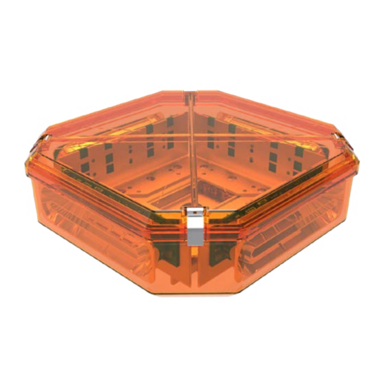
The ECCO LED DuoBeam™ uses state of the art LEDs and optics
to provide superior optical output. The rugged design and long
life capabilities make it virtually maintenance free. When properly
configured, the DuoBeam™ will exceed SAE Class 1 and California
Title 13 requirements.
Unpacking and Pre-Installation:
Carefully remove the lightbar and place it on a flat surface. Examine the unit for transit damage and locate all parts. If damage is found or
parts are missing, contact the transit company or ECCO. Do not use damaged or broken parts.
Ensure the lightbar voltage is compatible with the planned installation.
IMPORTANT!
Read all instructions before installing and using. Installer: This manual must be
delivered to the end user. This manual assumes installation by a suitably qualified Automotive Technician.
!
WARNING!
Failure to install or use this product according to manufacturer's recommendations may result in property
damage, serious bodily/personal injury, and/or death to you and those you are seeking to protect!
Do not install and/or operate this safety product unless you have read and understand the safety
information contained in this manual.
1. Proper installation combined with operator training in the use, care and maintenance of emergency warning devices are essential to
ensure the safety of emergency personnel and the public.
2. Emergency warning devices often require high electrical voltages and/or currents. Exercise caution when working with live electrical
connections.
3. This product must be properly grounded. Inadequate grounding and/or shorting of electrical connections can cause high current
arcing, which can cause personal injury and/or severe vehicle damage, including fire.
4. Proper placement and installation is vital to the performance of this warning device. Install this product so that output performance of
the system is maximized and the controls are placed within convenient reach of the operator so that s/he can operate the system
without losing eye contact with the roadway.
5. It is the responsibility of the vehicle operator to ensure daily that all features of this product work correctly. In use, the vehicle operator
should ensure the projection of the warning signal is not blocked by vehicle components (i.e., open trunks or compartment doors),
people, vehicles or other obstructions.
6. The use of this or any other warning device does not ensure all drivers can or will observe or react to an emergency warning signal.
Never take the right-of-way for granted. It is your responsibility to be sure you can proceed safely before entering an intersection, drive
against traffic, respond at a high rate of speed, or walk on or around traffic lanes.
7. This equipment is intended for use by authorized personnel only. The user is responsible for understanding and obeying all laws
regarding emergency warning devices. Therefore, the user should check all applicable city, state, and federal laws and regulations.
The manufacturer assumes no liability for any loss resulting from the use of this warning device.
8. This product may contain high intensity LEDs staring directly into these lights could result in temporary and/or permanent vision
impairment.
Installation and Operation Instructions
DuoBeam™
Page 1 of 12
Advertisement
Table of Contents

Related Manuals for Ecco DuoBeam


Summary of Contents for Ecco DuoBeam
- Page 1 Carefully remove the lightbar and place it on a flat surface. Examine the unit for transit damage and locate all parts. If damage is found or parts are missing, contact the transit company or ECCO. Do not use damaged or broken parts.
-
Page 2: Specifications
Mounting Before proceeding with installation, plan all wiring and cable routing. For orientation purposes, the DuoBeam™ was built with the carriage bolt track running from left to right (not front to back). The mounting location for the lightbar should be chosen such that the lightbar is level and visibility to approaching traffic is optimized. - Page 3 Magnet Mount 1. Insert carriage bolts into track. 2. Place oversized washers over bolts as shown in FIGURE 2. 3. Attach magnetic base over bolts. 4. Place lock washer and nut on bolt and tighten until secure. OVERSIZED WASHERS MAGNETIC BASE 5/16-18”...
- Page 4 3. Attach bracket assembly to mirror supports with U-bolts. Position bracket assembly as desired and tighten U-bolts. The DuoBeam™ mounting bracket should be parallel to the ground. 4. Insert two carriage bolts into underside of the DuoBeam™ bracket. Secure the unit to the top of the DuoBeam™ bracket. 7/16” LONG BOLT...
-
Page 5: Wiring Instructions
IF Series Wiring An IF series DuoBeam™ has a dedicated ground wire and one or more +power wires routed to the modules. The black ground wire should be connected directly to the battery. The amp ratings for each module type are detailed in the specifications secion of this installation guide. - Page 6 IF Series Flash Pattern Selection The DuoBeam can be populated with one of two different module types - PriZm™ or Torus™. For PriZm™ (8 or 12 LED) style modules, the flash pattern on each individual module can be cycled to the next flash pattern (shown in TABLE 1) by briefly shorting together the 2 short pads with a wire or the blade of a screwdriver as shown in FIGURE 5.
- Page 7 For Torus™ (6 or 9 LED) style modules, the flash pattern on each individual module can be cycled to the next flash pattern (shown in Table 2) by momentarily shorting together the JP1 pins with a wire or the blade of a screwdriver as shown in FIGURE 6. The module will reset to the default flash pattern when the JP1 pins are shorted together for 5 seconds or more.
- Page 8 TR Series Wiring A TR series DuoBeam™ has a single cable with 7 colored wires. A dedicated ground wire, a dedicated power wire and five colored control wires which run through the main driver board. The 16 AWG black ground wire should be connected directly to the battery. The 16 AWG red power wire requires a constant 10 to 16V(+) power source with a customer supplied in line 15A fuse.
- Page 9 Single Flash Simultaneous 250 FPM Single Flash Alternating 250 FPM Rotate Cruise TABLE 5 For instructions related to the California Title 13 steady burning red warning lamp requirement during level mode operation, please contact ECCO directly. Page 9 of 12...
-
Page 10: Replacement Parts/Accessories
TR9 (independent flashing) EZ21IF9X* REF8 (centrally controlled) EZ27CC8X* REF12 (centrally controlled) EZ27CC12X* REF8 (independent flashing) EZ27IF8X* REF12 (independent flashing) EZ27IF12X* *Where X indicates color options: A=Amber, B=Blue, C=Clear (White), G=Green, R=Red Contact ECCO for Multicolor Options. Page 10 of 12... -
Page 11: Troubleshooting
Options and Maintenance: Lens Cleaning Occasional cleaning of the lenses will ensure optimum light output. Take care when cleaning lenses - although tough, polycarbonate scratches easily. Clean the lens and base with soap and water or a lens polish using a soft cloth. Do not use solvents as they may damage the polycarbonate. - Page 12 Electronics Controls Company “ECCO” (Manufacturer) ECCO warrants that on the date of purchase, this product will conform to ECCO’s specifications for this product (which are available from ECCO upon request). This Limited Warranty extends for Sixty (60) months from the date of purchase.
Need help?
Do you have a question about the DuoBeam and is the answer not in the manual?
Questions and answers