Advertisement
Quick Links
!
WARNING!
Failure to install or use this product according to manufacturers recommendations may result in property damage,
serious bodily/personal injury, and/or death to you and those you are seeking to protect!
Do not install and/or operate this safety product unless you have read and understand the
safety information contained in this manual.
1. Proper installation combined with operator training in the use, care, and maintenance of emergency warning devices are
essential to ensure the safety of emergency personnel and the public.
2. Emergency warning devices often require high electrical voltage and/or current Exercise caution when working with live electrical
connections.
3. This product must be properly grounded. Inadequate grounding and/or shorting of electrical connections can cause high
current arcing, which can cause personal injury and/or severe vehicle damage, including fire.
4. Proper placement and installation are vital to the performance of this warning device. Install this product so that output
performance of the system is maximized and the controls are placed within convenient reach of the operator so that s/he
can operate the system without losing eye contact with the roadway.
5. It is the responsibility of the vehicle operator to ensure daily that all features of this product work correctly. In use, the
vehicle operator should ensure the projection of the warning signal is not blocked by vehicle components (i.e., open trunks
or compartment doors), people, vehicles, or other obstructions.
6. The use of this or any other warning device does not ensure all drivers can or will observe or react to an emergency warning signal.
Never take the right-of-way for granted. It is your responsibility to be sure you can proceed safely before entering an
intersection, driving against traffic, responding at a high rate of speed, walking on or around traffic lanes.
7. This equipment is intended for use by authorized personnel only. The user is responsible for understanding and obeying
all laws regarding warning signal devices. Therefore, the user should check all applicable city, state, and federal laws and
regulations. The manufacturer assumes no liability for any loss resulting from the use of this warning device.
Specifications:
Size:
Weight:
ED3307SA:
ED3307CB:
Input Voltage:
Peak Current @ 12.8 VDC:
Max Power @ 12.8 VDC:
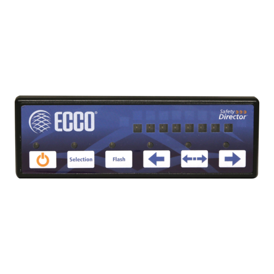
Figure 2
920-0438-00 Rev. A
Installation and Operation Instructions
Light stick:
48" x 3" x 2"
Control box:
6" x 3 3/4" x 3/4"
ED3307A:
17.7 lb.
18.2 lb.
0.5 lb.
12-24VDC
2.8A
35.8W
Safety Director Arrow
Wire the Safety Director:
Wire the Safety Director into the vehicle's 12 or 24 Volt system accord-
ing to Figure 1. Provide a 5A fuse near the power take off.
Use 16AWG wire or larger for the Red and Black wire connections.
Route the lightbar cable from the Stick to the Control Box and plug
them together.
BATT(+)
CONTROL
BOX
Unpacking:
Carefully remove the unit and place it on a flat surface.
Examine the unit for transit damage, etc. If the vehicle
has an electrical system other than 12 or 24 Volts DC
negative ground, contact your local representative or call the
manufacturer for instructions.
FUSE
5 AMP
RED
LIGHTBAR CABLE
BLACK(-)
Figure 1
STICK
Page 1 of 8
Advertisement

Related Manuals for Ecco ED3307 Series


Summary of Contents for Ecco ED3307 Series
- Page 1 Installation and Operation Instructions Safety Director Arrow WARNING! Failure to install or use this product according to manufacturers recommendations may result in property damage, serious bodily/personal injury, and/or death to you and those you are seeking to protect! Do not install and/or operate this safety product unless you have read and understand the safety information contained in this manual.
-
Page 2: Wiring Instructions
Mounting: The Safety Directors are vertical surface mounted by screwing through the mounting bracket. Additionally, the Split Arrow is attached by bolts in the channel on the back of each light bar, opposite the arrows. 1. The light bar(s) should be mounted to a flat surface or one with the least amount of curvature. Determine the proper mounting height for the light bar(s) that allows maximum visibility of the warning device to other road users and sufficient wire access. - Page 3 PATTERN GROUP FLASH PATTERN ONE LAMP SEQUENCE TO DOUBLE FLASH TWO LAMP SEQUENCE TO DOUBLE FLASH SIX LAMP SEQUENCE TO DOUBLE FLASH SEQUENCE TO SOLID ONE LAMP SEQUENCE TO TRIPLE FLASH TRIPLE LAMP SEQUENCE DOUBLE FLASH SEQUENCE ON TO SEQUENCE OFF SOLID ARROW Group 1_ONE LAMP SEQUENCE TO DOUBLE FLASH RIGHT...
- Page 4 Group 3_SIX LAMP SEQUENCE TO DOUBLE FLASH RIGHT CENTER FLASH LEFT Group 4_SEQUENCE TO SOLID RIGHT CENTER LEFT FLASH 920-0438-00 Rev. A Page 4 of 8...
- Page 5 Group 5_ONE LAMP SEQUENCE TO TRIPLE FLASH RIGHT CENTER FLASH LEFT Group 6_ TRIPLE LAMP SEQUENCE DOUBLE FLASH CENTER RIGHT FLASH LEFT 920-0438-00 Rev. A Page 5 of 8...
- Page 6 Group 7_ SEQUENCE ON TO SEQUENCE OFF RIGHT CENTER FLASH LEFT Group 8_SOLID ARROW CENTER RIGHT FLASH LEFT Note: Group 8 RIGHT, LEFT, and CENTER are SAE J595 compliant. 920-0438-00 Rev. A Page 6 of 8...
- Page 7 FLASH WITH NO ARROWS Learn more about emergency and warning lighting on our website.
Need help?
Do you have a question about the ED3307 Series and is the answer not in the manual?
Questions and answers