
Related Manuals for Frico SWX CE Series


Summary of Contents for Frico SWX CE Series
- Page 1 Original instructions SWX CE ... 7 ... 12 ... 17 ... 22 ... 27 ... 32 ... 37 ... 42 ... 47 ... 52...
- Page 2 SWX CE SWX CE min 150 ØI [mm] ØI SWXCE12 R3/4” SWXCE22 R1” Electrical installation 230V~ Terminal box 0,85 m cable...
- Page 3 SWX CE Accessories HxWxD Type [mm] SWXHFT1 SWXCE12 455x525x15 SWXHFT2 SWXCE22 595x650x15 SWXHFT Controls SWX CE Type RSK-nr NRF-nr HxWxD (SE) (NO) [mm] SWXRT35 175x150x100 SWXRT35 Water regulation SWX CE Type RSK-nr NRF-nr (SE) (NO) 672 70 37 85 021 57 SD20* 672 70 35 85 021 47...
- Page 4 SWX CE Wiring diagrams SWX CE Internal SWX CE/CS -12, -22 SWXD -13, -23 BK BU WT RD SWX CE Control by thermostat only SWXCE/CS -12, -22 SWXCE/CS -12, -22 SD20* SD20* TVV20/25* TVV20/25* BK BU WT RD BK BU WT RD *) Note! Only for mounting outside corrosive environment.
- Page 5 SWX CE SWX CE ∆t* Heat Airflow Airflow Sound Water Voltage Amperage Weight output* level* throw volume* [°C] [kW] [m³/h] [m³/s] [dB(A)] [kg] SWXCE12 12 2100 230V~ SWXCE22 24 4200 230V~ 1,35 ) Applicable at water temperature 60/40 °C, air temperature, in +15 °C. ) Conditions: Distance to the unit 5 metres.
- Page 6 SWX CE Output charts water SWX CE Incoming / outgoing water temperature 90/70 °C Air temp. in = +5 °C Air temp. in = +15 °C Type Airflow Output Air temp. Water flow Pressure Output Air temp. Water Pressure drop flow drop [m³/h]...
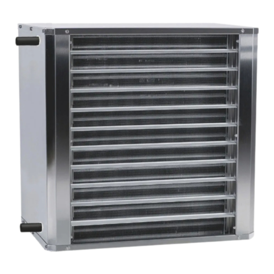
- Page 7 SWX CE Installation and operating instructions • Meets the requirements for corrosion class General Instructions C5-M. Read these instructions carefully before • Uses hot water as the energy medium. installation and use. Keep this manual for • Casing, air deflector grille and brackets future reference.
- Page 8 SWX CE 3. The fan heater is fitted with a transport protection that is attached to the top and bottom. Loosen the four screws that have the Torx 20 head as shown in Figure C and remove the transport guard. Replace the screws, see figure D.
- Page 9 SWX CE Connection of heating coil The installation must be carried out by an authorised installer. 1. The fan heater must not be connected to the hot mains water or steam. The maximum permissible temperature and pressure are indicated on the fan heater type plate at the connection pipes.
-
Page 10: Maintenance
SWX CE Maintenance To ensure performance and reliabilty of the unit, inspection and cleaning should be carried out reguarly. Inspection should be carried out at least twice a year. Clean the unit when needed. During inspection the power supply must always be disconnected. - Page 11 SWX CE Safety • Ensure that the area around the intake is kept free from material which could prevent the air flow through the appliance. • Lifting aids should be used to lift the appliance. • The unit is unpainted and may have sharp metal edges.
- Page 12 Main offi ce Frico AB Tel: +46 31 336 86 00 Box 102 SE-433 22 Partille mailbox@frico.se Sweden www.frico.se For latest updated information and information about your local contact: www.frico.se...
Need help?
Do you have a question about the SWX CE Series and is the answer not in the manual?
Questions and answers