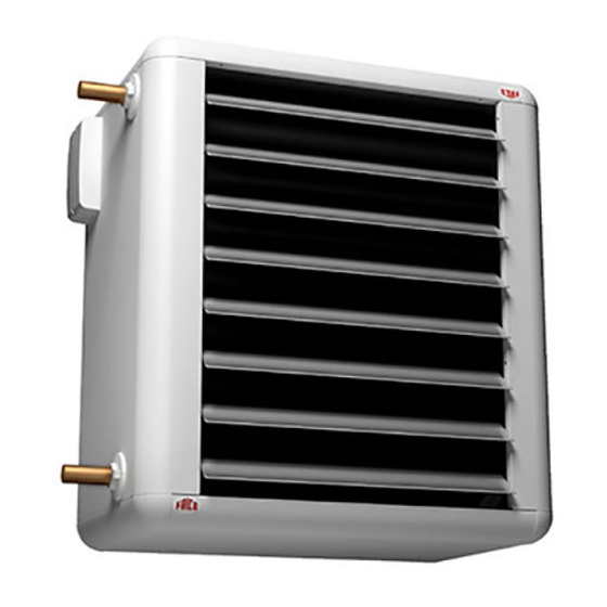
Frico SWH Series Manual
Hide thumbs
Also See for SWH Series:
- Manual (32 pages) ,
- Manual (33 pages) ,
- Assembly and operating instructions manual (56 pages)
Subscribe to Our Youtube Channel
Summary of Contents for Frico SWH Series
- Page 1 ... 21 ... 27 ... 33 ... 24 ... 30 ... 37 ... 40 ... 47 ... 50 ... 53 ... 43...
- Page 2 Fan heater SWH Fan heater SWH Mounting brackets SWB Basic filter SWFTN Filter section, deep-pleated bagfilter EU3 Return air intake SWD Mixing cabinet with damper SWBS Outer wall grill SWY Extra air director, adjustable louvres SWLR Fläktluftvärmare SWH Monteringskonsoler SWB Trådnätsfilter SWFTN Filterskåp, djupveckad filterkasset EU3 SWF...
- Page 3 Dimensions Inlet Outlet ø Type Ø [mm] [mm] [mm] [mm] [mm] [mm] [mm] [mm] [mm] [mm] [mm] [mm] SWH02 SWH12 SWH22 SWH32/33 Outer wall grill, SWY Mounting brackets SWB Filter section, SWF ø20 42,3 Type Type Type [mm] [mm] [mm] [mm] [mm] [mm]...
- Page 4 Control SWH SIRe Basic SIRe Competent Modular cables SIReUB1, Integrated Modular cable control unit Basic control card SIReUA1, SIReC1X, Base in SWH control unit control card HUB Integrated control Competent and Competent card Base in SWH Advanced SIRe Advanced For Advanced with mixing cabinet - SIReFAWM also includes damper...
- Page 5 SDM24 TBVCM SDM24 VMOP TBVCMP SD230 TBVC BPV10 SD230 VOSP TBVCMP BPV10 SD230 TRVS SDM24 TRVS...
- Page 6 Type RSK-nr Description Flow Voltage Connection Kvs VMO15LF 673 09 47 Modulating valve kit Low flow 24 V DN15 0,40 VMO15NF 673 09 48 Modulating valve kit Normal flow 24 V DN15 VMO20 673 09 49 Modulating valve kit Normal flow 24 V DN20 VMO25...
- Page 7 Wiring diagrams SWH Internal SWH02-22 SWH32-33 Yellow-green SWH02 SWH12 SWH22 TB TB Z1U2 U1 Z2 PE 100 V 80 V 100 V Transformer 100 V 125 V 125 V 140V 125 V 150V Transformer 150 V 165V 150V 230 V 230 V 230 V F5 F4...
- Page 8 Wiring diagrams SWH...
- Page 9 ALARM OUT (BMS) (potential free contact, max 3A, 230V) EXTERNAL ON/OFF 5-30V AC/DC EXTERNAL RPM 0-10V DC IN EXTERNAL ALARM IN (potential free contact) EXTERNAL SETBACK TEMP. ON/OFF (potential free contact)
- Page 12 Technical specifications | 2 Fan heater SWH with water heat Type RSK-nr Heat output * Air flow* Air flow* Sound level ∆t* [kW] [m³/h] [m³/s] [dB(A)] [°C] SWH02 672 68 79 530 - 1120 0,15 - 0,31 26 - 39 SWH12 672 68 89 840 - 1810...
- Page 13 Output charts water...
- Page 14 Output charts water...
- Page 15 Output charts water...
- Page 16 Output charts water...
- Page 21 Assembly and operating instructions General Instructions Mounting Read these instructions carefully before The unit is delivered with casing, fan, heating installation and use. Keep this manual for coil and air director as standard. Mounting future reference. brackets are orded separately. The product may only be used as set out in Can be mounted on the wall for horisontal the assembly and operating instructions.
- Page 22 the filter is slid down behind the coil in tracks The control system is preinstalledin the fan for this purpose. The filter can be reached for heater with an integrated control card. SIRe is installation and cleaning/maintenance from supplied pre-programmed with quick-release both top or bottom of the unit.
- Page 23 Filter Safety If used, the basic filter should be cleaned • Ensure that the area around the intake is when necessary and checked at least 4 times kept free from material which could a year. To clean the filter, open top or bottom prevent the air flow through the lid by loosening a pair of screws underneath appliance!
- Page 24 Main offi ce Frico AB Tel: +46 31 336 86 00 Box 102 Fax: +46 31 26 28 25 SE-433 22 Partille mailbox@frico.se Sweden www.frico.se For latest updated information and information about your local contact: www.frico.se...


Need help?
Do you have a question about the SWH Series and is the answer not in the manual?
Questions and answers