Table of Contents
Advertisement
Quick Links
Advertisement
Table of Contents

Related Manuals for Tenma DSO


Summary of Contents for Tenma DSO
- Page 2 Introduction Dear valued customer, Thank you for purchasing a Tenma instrument. To use your new product correctly, make sure you read this User Manual carefully and completely before operation and pay particular attention to the Safety Instructions “ ” section Please keep this User Manual in a safe place after reading it carefully.
- Page 3 The Company reserves the right to change product specifications and prices. all rights reserved. All licensed software products are properties of Tenma, its subsidiaries or supplier They are protected by the national copyright law and international conventions. Information contained in this manual supercedes all information in previously published versions.
- Page 4 TENMA shall pay the cost of returning the product to the destination, all freight, custom duty, tax and other costs will If any genuine defect is found during the valid warranty be paid by the customer.
- Page 5 To avoid fire and personal injury be the only and all remedial measure offered by TENMA. Notwithstanding any prior notification of potential damage Use a correct power cable Use only the specified power that is indirect, special, consequential or inevitable, TENMA cable which is authorized in the country of use.
- Page 6 Tenma DSO Four-channel User Manual Remove the plug correctly Do not remove the Use suitable fuses Only use specified fuse types probe or testing cable when they are connected to and rated specifications. power. Avoid exposing circuitry When power is on, never make...
- Page 7 Tenma DSO Four-channel User Manual appear on the product Warning Warning statements identify conditions or practices that could result in injury or loss of life Caution Caution statements identify conditions or practices that could result in damage to t his unit...
- Page 8 Chapter 1 User Guide Simple guide to oscilloscope functions and installation Chapter 2 Instrument Setups Guide to operation of the Tenma DSO four channel digital storage oscilloscope. Chapter 3 Practical Illustrations Example illustrations are provided to solve various testing problems...
- Page 9 Tenma DSOfour-channel digital storage oscilloscope offer user-friendliness, outstanding technical indicators a a host of advanced features. They are your perfect tools to complete testing tasks swiftly and efficiently. This manual is a user guide for the Tenma DSO digital storage oscilloscope : Model...
- Page 10 Tenma DSO Four-channel User Manual Tenma DSO four-channel digital storage oscilloscope 24k storage depth;60M equivalent storage offer a user-friendly front panel with clear indications depth;1024k recording length to allow access to all basic functions for easy Unique envelop sampling feature with direct operation.
- Page 11 Tenma DSO Four-channel User Manual Edge, video, pulse, slope and alternate trigger 2x multimeter test lead; 2x c urrent -to-voltage functions converter module: UT M03/UT-M04 Automatic measurement of 24 waveform parameters parameters testing and customization Multiple AUTO setups for extra flexibility...
-
Page 12: Table Of Contents
Tenma DSO Four-channel User Manual Table of Contents Item Page Safety Instructions Preface Chapter 1 User Guide------------------------------------------------------------------------------ General Inspection---------------------------------------------------------------------- Functional Check ----------------------------------------------------------------------- Probe Compensation ------------------------------------------------------------------ Automatic Setup for Waveform Display ---------------------------------------------- Getting to Know the Vertical System -------------------------------------------------- Getting to Know the Horizontal System... - Page 13 Tenma DSO Four-channel User Manual Item Page Utility Function Setup --------------------------------------------------------------- Automatic Measurement----------------------------------------------------------- Cursor Measurement --------------------------------------------------------------- Using the Run/Stop --------------------------------------------------------------------- Auto Setup------------------------------------------------------------------------------ Multimeter Measurement ---------------------------------------------------------- Help System--------------------------------------------------------------------------- Chapter 3 Practical Example Illustrations -------------------------------------------------------- Illustration 1 : Measuring simple signals ---------------------------------------------...
-
Page 14: Item Page
Chapter 5 Upgrading System Software on USB ---------------------------------------------------- Chapter 6 Technical Indicators -------------------------------------------------------------------------------- Appendix A: Technical indicators -------------------------------------------------------------- Appendix B : Accessories for Tenma DSO Four-channel Digital Storage Oscilloscope ------------------------------------------------------------------------- Appendix C : Maintenance and Cleaning----------------------------------------------- Appendix D Factory Setups -------------------------------------------------------... -
Page 15: Chapter 1 User Guide
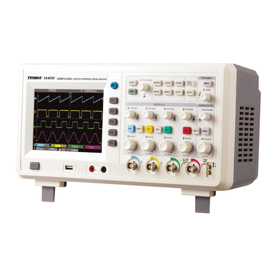
Yo u r Tenma DSO F o u r - c h a n n e l d i g i t a l s t o r a g e Your Tenma DSO Four-channel oscilloscope comes with oscilloscope is a small and compact benchtop device. - Page 16 Tenma DSO Four-channel User Manual 200MH z 2GS/ s DIGI T AL STORAGE OS CI LLOSCOP E Figure 1-1 Tenma DSO Four-cha Digital Storage Oscilloscope...
- Page 17 Tenma DSO Four-channel User Manual External trigger USB device communication channel interface Figure 1-2 Back cover of Tenma DSO four-channel digital storage oscilloscope...
- Page 18 Tenma DSO Four-channel User Manual Multifunction Frequently knob Used Menus 72-8727 TRIGGER 200M Hz 2G S/ s DIG ITAL ST O RA GE O SCIL L OSCOPE CLOSE MEASURE ACQ UIRE STORAGE RUN/STOP MENU ME NU Trigger controls O N/ OF F...
- Page 19 Tenma DSO Four-channel User Manual Displaying the horizontal trigger position Trigger frequency counter Trigger status display The menu varies with individual function keys Channel vertical reference Waveform display window Channel vertical attenuation range Displaying main Trigger level time base setup...
-
Page 20: General Inspection
Tenma DSO Four-channel User Manual test, please contact your TENMA dealer or our local General Inspection office. We suggest checking your new Tenma DSO Four- In the event of any shipping damages, please retain oscilloscope in the following steps. channel the packaging and notify our shipping department or 1. - Page 21 Tenma DSO Four-channel User Manual 1. Power on the unit Power on the unit. AC power supply voltage range is 1 0 0 V t o 2 4 0 V, f re q u e n c y 4 5 H z -4 4 0 H z . Af t e r...
- Page 22 Yo u r Tenma DSO F o u r - c h a n n e l d i g i t a l s t o r a g e the attenuation switch of the probe to...
- Page 23 Tenma DSO Four-channel User Manual You have to set the probe attenuation factor of Connect the probe tip and ground clamp to the the oscilloscope. This factor changes the vertical connection terminal for the probe compensation range multiple to ensure the measurement result signal.
-
Page 24: Probe Compensation
Tenma DSO Four-channel User Manual Observe the displayed waveform. Probe Compensation When connecting the probe to any input channel for the first time, perform this adjustment to match the probe to the channel. Skipping the compensation calibration step will result in measurement error or fault. Please adjust probe... -
Page 25: Automatic Setup For Waveform Display
Getting to Know the Vertical System Yo u r Tenma DSO F o u r - c h a n n e l d i g i t a l s t o r a g e As shown in the figure below, there are a group of oscilloscope features an auto setup function. - Page 26 Tenma DSO Four-channel User Manual POSITION knob move the waveform Measurement Tips : vertically. Press this knob to quickly return to the If the channel coupling is DC, you can measure the centre point signal s DC component quickly by checking the...
-
Page 27: Getting To Know The Horizontal System
Tenma DSO Four-channel User Manual POSITION knob can move all channels MATH Getting to Know the System Horizontal waveforms and REF waveforms horizontally Press As shown in the figure below, there are one button this knob to quickly return to the centre point and two knobs in the horizontal control zone. - Page 28 Tenma DSO Four-channel User Manual Use the horizontal POSITION knob to adjust Shortcut key for resetting the trigger point to horizontal position waveform horizontal zero : window. When the horizontal POSITION knob is When the trigger point has shifted significantly away...
-
Page 29: Getting To Know The Trigger System
Tenma DSO Four-channel User Manual Trigger LEVEL knob Getting to Know the Trigger System When operating edge, pulse width and slew rate As shown in Figure 1 13 there are one knob and triggers, set the amplitude to be crossed by the one button in the trigger menu control zone. - Page 30 Tenma DSO Four-channel User Manual Pre s s [ ] an d s e l e ct f o r [ SI G NAL Notes : SOURCE ] (Turn the MULTIPURPOSE control knob to select and then press that key to I c o n u t i l i t y f u n c t i o n o f t h e confirm).
-
Page 31: Chapter 2 Instrument Setups
UTILITY vertical controls, horizontal controls and trigger Automatic measurement ([ MEASURE s ys t em me n u of yo u r Tenma DSO F o ur - c h a n n Cursor measurement ([ CURSOR oscilloscope by now. After reading the last chapter,... -
Page 32: Setting The Vertical System
Tenma DSO Four-channel User Manual Setting the Vertical System CH1, CH2, CH3, CH4 and setups Each channel has its own vertical menu. You should set up each item for each channel individually. Press the ], [ ], [ ] or [ ] function button and the system will display the operation menu for CH1, CH2, CH3 or CH4. - Page 33 Tenma DSO Four-channel User Manual 1. Setting up channel coupling : Press [ ] twice to select DC 1M Both DC and AC Take an example of applying a signal to CH1. The quantities of the testing signal being inputted to...
- Page 34 Tenma DSO Four-channel User Manual Press [ ] then [ ] to select ground. It is now set up 2. Setting the channel bandwidth limit as ground. The waveform display is as follows : Take applying a signal to Ch1 as an example, the s i g n al t o b e t e s t e d c o n t a i n s h i gh f re q u e n cy quantities.
- Page 35 Tenma DSO Four-channel User Manual Press [ ] then [ ]. The noise and high frequency 3. Setting up the probe rate quantities over 20MHz of the signal being tested are To match the probe attenuation factor setup, it is now restricted.
- Page 36 Tenma DSO Four-channel User Manual 4. Vertical VOLTS/DIV adjustment setup 5. Waveform inversion setup You can adjust the VOLTS/DIV range of the vertical Waveform inversion : The displayed signal is inverted deflection factor either in the coarse tune mode or 180 degrees.
- Page 37 Tenma DSO Four-channel User Manual Operating Math Functions Math functions are displays of and FFT mathematical results of waveform channels CH1, CH2 , CH3 a nd CH4, an d t he d igi tal ly f il tered waveform. The menu is as follows :...
- Page 38 Tenma DSO Four-channel User Manual Table 2-2a Explanatory notes for the Math menu (1) Function Menu Setup Explanatory Note Type Math To carry out functions Sou rce 1 Source 1 as CH 1 waveform Source 1 as CH 2 waveform...
- Page 39 Tenma DSO Four-channel User Manual Table 2-2b Explanatory notes for the Math menu (2) Function Menu Setup Explanatory Note Compress Scale the waveform by ratio. There are four r ati os to choose 1/10 from : 1/1, 1/10, 1/100, 1/1000...
- Page 40 Tenma DSO Four-channel User Manual FFT spectrum analysis By using the FFT (Fast Fourier Transform algorithm you can convert time domain signals into Fundamental frequency domain signals With FFT you can frequency component 1 MHz conveniently observe the following types of...
- Page 41 Tenma DSO Four-channel User Manual Table 2-3a Explanatory notes for the FFT menu (1) Function Menu Setup Explanatory Note Type To carry out FFT algorithm functions Sou rce Set C H1 as math waveform Set C H2 as math waveform...
- Page 42 Tenma DSO Four-channel User Manual waveform by one window function to set the value to 0 How to use FFT functions for start and finish compulsively. For application of the Signals with DC quantities or DC offset will cause window function, please see the table below : error or offset of FFT waveform quantities.
- Page 43 Tenma DSO Four-channel User Manual Table 2-4 FFT Window Feature Most Suitable Measurement Item Rec tangle The best frequency recognition rate Temporary or fast pulse. Si gnal level is generall y the worst amplitude recognition rate the same befor e and after. Equal sine wave of very Basically similar to a status without similar frequency.
- Page 44 Tenma DSO Four-channel User Manual Digital Filtering Function Table 2-5a Explanatory notes for the digital filtering menu (1) Function Menu Setup Explanatory Note Type Filter Digital filtering Set C H1 as filter target Set C H2 as filter target Source...
- Page 45 Tenma DSO Four-channel User Manual Table 2-5b Explanatory notes for the digital filtering menu (2) Function Menu Setup Explanatory Note Effective only during low-pass filtering or band-pass filtering. ---- Upp er Limit Use the MULTIPU RPOSE control knob to set the maximum...
- Page 46 Display of the saved reference waveforms can be set To close the reference waveform, press [ on or off in the REF menu. The waveforms are saved In actual application, when using your Tenma DSO in the non volatile memory of the oscilloscope or an Four-channel...
- Page 47 Tenma DSO Four-channel User Manual Table 2-6a Explanatory notes for the REF menu (1) Function Menu Setup Explanatory Note Ref Wave REF A Select R EF A as the reference waveform REF B Select R EF B as the reference waveform...
- Page 48 Tenma DSO Four-channel User Manual Table 2-7 Explanatory notes for the USB menu Function Menu Setup Explanatory Note File name Use the MULTIPUR POSE control knob and key to set the document name to be i mported from the USB device.
-
Page 49: Setting The Horizontal System
Tenma DSO Four-channel User Manual Setting the Horizontal System to change horizontal time base ratitude and use the horizontal POSITION knob to change Horizontal Control relative position if the triggering point on the screen For instructions on how to display the... - Page 50 Tenma DSO Four-channel User Manual Table 2-8 Explanatory notes for the horizontal menu Function Menu Setup Explanatory Note Window ---- Press [ ] to swi tch between the “ main screen and ” “ expanded window ” Dua l Xbase Enter the dual time base menu.
- Page 51 Tenma DSO Four-channel User Manual Window Expansion The window expansion setting cannot be slower than the main time base setting. Maximum magnification Window expansion can be used to zoom in a band of multiple is 100x. waveform to check image details. Please refer to In the window extension mode, the display is divided Figure 2-14.
- Page 52 Tenma DSO Four-channel User Manual Dual Time Base Function The dual time base function is similar to window extension but there is a fundamental difference In Delayed time the window extension mode you can magnify the base M2 waveform times...
- Page 53 Tenma DSO Four-channel User Manual Table 2-9 Explanatory notes for the dual time base menu Function Menu Setup Explanatory Note Main Switching between mai n time base and dual time base Mode Dual For dual time base mode instructi ons see Figure 2- 15...
-
Page 54: Setting The Trigger System
Tenma DSO Four-channel User Manual LEVEL knob to change the trigger point s vertical Setting the Trigger System position on the trigger edge, i.e. the intersection point Triggering decides when the oscilloscope collects of the trigger level line and the signal edge on the data and display waveforms. - Page 55 Tenma DSO Four-channel User Manual Table 2-10 Edge trigger Function Menu Setup Explanatory Note Type Edge Source Ch1, CH2, CH3, CH4 Set CH1, CH2, CH3 or CH4 as the signal source trigger signal EXT, EXT/5 Set to external trigger or divide the external trigger source by 5...
-
Page 56: Setting The Sampling System
Tenma DSO Four-channel User Manual Table 2-10 Edge trigger Connected to the table Function Menu Setup Explanatory Note Slo pe Rise S e t to t ri g g er at th e s i g na l s r i si ng e d ge... - Page 57 Tenma DSO Four-channel User Manual Table 2-11 Pulse width Trigger Function Menu Setup Explanatory Note Auto Mod e The system automatically acquires waveform data w hen there i s no trigger signal . The scan basel ine i s shown on the displ ay.
- Page 58 Tenma DSO Four-channel User Manual Table 2-1 Pulse width setup Function Menu Setup Explanatory Note Typ e Pulse wi dth Setting Set pulse wi dth trigger to 20.0ns-10s with the MULTIPURPOSE control knob Back ---- Return to the pul se width trigger menu...
- Page 59 Tenma DSO Four-channel User Manual Table 2-14 Video Setup Function Menu Setup Explanatory Note Sta ndard Suitable for PAL video signals NTSC Suitable for NTSC video signal s Sync Odd Field Set the video odd fi eld to synchroni zed trigger...
- Page 60 Tenma DSO Four-channel User Manual Slope trigger If slope trigger is selected, trigger occurs when the signal s rising or falling rate meets the set condition. For the trigger menu see Table 2-15 below Figure 2-17 Video trigger : Field synchronization...
- Page 61 Tenma DSO Four-channel User Manual Table 2-15 Slope trigger Function Menu Setup Explanatory Note Type Slew rate Source Ch1, CH2, CH3, CH4 Set CH1, CH2, CH3 or CH4 as the signal source trigger signal EXT, EXT/5 Set to external trigger or divide the external trigger source by 5...
- Page 62 Tenma DSO Four-channel User Manual Table 2-16 Slew rate setup Function Menu Setup Explanatory Note Pol arity Rise Select the ri sing edge w ithin the thr eshold for trigger Fall Select the falli ng edge w ithin the threshold for trigger...
- Page 63 Tenma DSO Four-channel User Manual Adjusting the Holdoff Time Yo u ca n a d j u s t t h e h o l d o f f t i m e t o o b s e r ve complicated waveforms (e.g.
- Page 64 Tenma DSO Four-channel User Manual Operation Definitions Trigger source The signal used for trigger. 1. Follow the normal signal synchronization The signal for trigger can be obtained from procedure and select the edge and trigger source in various sources : input channel (CH1, CH2, CH3,...
- Page 65 Tenma DSO Four-channel User Manual LINE means the AC power source This signal. When the trigger signal is generated, trigger mode is suitable for observing signals trigger scan occurs. related to the AC power the correlation Single Trigger In this mode...
- Page 66 Tenma DSO Four-channel User Manual Pretrigger/Delayed Trigger Data sampled Setting the Sampling System before after triggering As shown below, [ ACQUIRE ] button in the control The t rigg er po si tion i s typicall y set at the zone is the function key for the sampling system.
- Page 67 Tenma DSO Four-channel User Manual Table 2-18 Sampling menu Function Menu Setup Explanatory Note Normal Acquisition Ordinar y sampli ng mode Peak Peak detect mode Averag e Set to average sampl ing with display of the average number of times...
- Page 68 Tenma DSO Four-channel User Manual Notes : Use Real time sampling observe single signals Use Equivalent sampling observe high frequency cyclical signals. To avoid mixed envelop when observing a signal, select Peak Detect To reduce random noise displayed signal select...
- Page 69 Tenma DSO Four-channel User Manual Definitions : Average mode The oscilloscope acquires several waveforms and take the average value to display Real time sampling Acquiring the data required in the final waveform You can use this mode to one go. Maximum sampling rate is 2GS/s.
-
Page 70: Setting The Display System
Tenma DSO Four-channel User Manual Setting the Display System Press the [ DISPLAY ] button to pop out the setup menu shown below. You can use this menu to adjust As shown below, the [ DISPLAY ] key in the control the display mode. - Page 71 Tenma DSO Four-channel User Manual Table 2-1 Display menu Function Menu Setup Explanatory Note Fu ll gra titude Set the grid displ ay mode of the waveform zone to full, grid, Grid Cross Hai r or frame Cross Hair Frame...
- Page 72 Tenma DSO Four-channel User Manual X-Y Mode Caution : In the normal mode, you can move figures This mode offers two separate displays. The first horizontally with the CH1 or CH3 POSITION knob group is CH1 and CH2, i.e. CH1 signal input on the...
-
Page 73: Storage And Recall
Tenma DSO Four-channel User Manual Key points : Storage and Recall Display Type Vector display fills the space As shown below, the [ STORAGE ] button in the control between adjacent sampling points in display. The dot zone is the function key for the storage system... - Page 74 Tenma DSO Four-channel User Manual Instructions : Note Press [ STORAGE to go to the type menu. There About “ Internal ” “ ” formats When are three types to choose from : Setting, Wave, exporting “ reference waveform ”...
- Page 75 Tenma DSO Four-channel User Manual Table 2-21 USB menu Function Menu Setup Explanatory Note File name Set the document name to be impor ted from the USB device w ith MU LTIPURPOSE control knob and key For specific steps see note...
- Page 76 Tenma DSO Four-channel User Manual Table 2-22 Save setup menu Function Menu Setup Explanatory Note Loa d Recall 10 internal save positions and select one of them wi th the 1~10 MULTIPURPOSE control knob Press the MULTIPURPOSE control knob to confirm...
- Page 77 Tenma DSO Four-channel User Manual 3. Select bitmap to enter the bitmap export menu See Table 2-24 Note : A bitmap can only be exported to a USB device. Table 2-24 Bitmap export menu Function Menu Setup Explanatory Note Bitmap...
-
Page 78: Utility Function Setup
Tenma DSO Four-channel User Manual Utility Function Setup As shown below, the [ UTILITY ] key in the control zone is the function key for utility functions. Figure 2-25 Function key for the sampling system (function) Press the [ UTILITY ] key to pop out the setup menu for utility functions. - Page 79 Tenma DSO Four-channel User Manual Table 2-26 Utility menu Function Menu Setup Explanatory Note Con figure Se lf Cal Run auto system calibration Ve rsion Display information like oscill oscope model, ver sion and serial number Era se Clear all saved reference waveforms and setups RTC Setup Enter date and time setup.
- Page 80 Tenma DSO Four-channel User Manual Table 2-27 Utility menu Function Menu Setup Explanatory Note Cymometer ON /OFF Displayed at the top right corner of the screen when turned on. See note Interface Set GPIB and LAN for communi cation. Appl icable for opti onal...
- Page 81 Tenma DSO Four-channel User Manual Table 2-28 Waveform record menu Function Menu Setup Explanatory Note ■F(4) Stop recording F(3) Playback button 1. When you press this button the system plays back and displays the number of screens to be played back. By turning the MULTIPURPOSE control knob, you can suspend playback.
- Page 82 Tenma DSO Four-channel User Manual Table 2-29 RTC setup Real Time Clock Function Menu Setup Explanatory Note Dis play On/Off Turn on the time displ ay. Time displ ay is di sabled when the frequency counter is in use Min&Hour...
- Page 83 Tenma DSO Four-channel User Manual Unlock : In Auto mode the setup will go back to Important Points : default for auto setup. Auto Calibration : You can correct measurement Locked : In Auto mode the current status is locked for errors caused by environmental changes with the auto setup.
-
Page 84: Automatic Measurement
Tenma DSO Four-channel User Manual Automatic Measurement As shown below, the [ MEASURE ] key is the function key for auto mea surement. Read the fol lowing instructions to familiarize with all the powerful automatic measurement functions of your Tenma DSO... - Page 85 Tenma DSO Four-channel User Manual Table 2- Measurement menu Function Menu Setup Explanatory Note The risi ng edge or fall ing edge time interval of a random channel Delay Phase waveform. See Table 2-33 ---- ---- ---- Pre 2/2 Confirm your setting and r eturn to the Utility menu...
- Page 86 Tenma DSO Four-channel User Manual Note Automatic measurement of voltage parameters Customised parameters are for quick parameter Four-channel Your Tenma DSO Oscill oscope can measurement . The measure ment men u of your a u t o m a t i c a l l y m e a s u r e t h e f o l l o w i n g v o l t a g e...
- Page 87 Tenma DSO Four-channel User Manual Preshoot : The ratio value of the difference between Positive Pulse Width (+Width) : The pulse width when minimum value and base value to the amplitude positive pulse is at 50% amplitude. value. Negative Pulse Width (-Width) : The pulse width when Average : Average amplitude of signals within 1 cycle.
-
Page 88: Cursor Measurement
Tenma DSO Four-channel User Manual Cursor Measurement Press [CURSOR] to display the measurement cursor and cursor menu, then adjust the cursor position by turning the MULTIPURPOSE control knob shown in the figure below CURSOR in the control zone function cursor... - Page 89 Tenma DSO Four-channel User Manual Table 2- 34 T ime cursor measurement menu Function Menu Setup Explanatory Note Typ e Time Measure time w ith the cursor Mod e Indep endent Move any one of the two cursors Tracking Move two cursors simultaneously w ithout changing...
-
Page 90: Using The Run/Stop
Tenma DSO Four-channel User Manual RUN/STOP Using the Run Button Acquire waveform continuously or stop acquisition. There is a button on the top right corner on the front If you want the oscilloscope to acquire waveform panel : [ RUN/STOP ]. -
Page 91: Auto Setup
Tenma DSO Four-channel User Manual Auto Setup : As shown above, Auto Setup can simplify operation. base range according to the amplitude and frequency of the waveform, and ensure stable display of the Press [ AUTO ] and the oscilloscope can automatically waveform. -
Page 92: Multimeter Measurement
Tenma DSO Four-channel User Manual Menu Display ON/OFF : select an appropriate range. If you are not certain a bo ut th e cu rre nt be in g t est e d, mak e an To display or hide the current menu... - Page 93 Tenma DSO Four-channel User Manual Table 2- DMM Menu Function Menu Setup Explanatory Note Funtion ON /OFF DMM functions on/off Mod e Voltag e Activate the voltage measurement function. Maximum measurement value for DC voltage is 400V. Maximum measurement val ue for AC...
-
Page 94: Chapter 3 Practical Example Illustrations
Tenma DSO Four-channel User Manual Voltage and time parameters for automatic Chapter Practical Example measurement Illustrations Your oscilloscope can automatically measure m o s t d i sp l a y s i gn a l s . To me a s u re s i gn a l... -
Page 95: Illustration 2 : Observing The Delay Caused By A Sine Wave Signal Passes Through The Circuit
Tenma DSO Four-channel User Manual Peak-to-peak and frequency measurements will now Illustration 2 : Observing the delay caused by a appear at the bottom of the screen, as shown in sine wave signal passes through the circuit Figure 3-1. As in the previous scenario, set the probe attenuation factor of the probe and oscilloscope channel to 10X. - Page 96 Tenma DSO Four-channel User Manual Observing the delay caused by a sine wave signal passes through the circuit and observing waveform changes. When measuring channel delay automatically : Press [ MEASURE ] to display the automatic measurement menu. Press [ ] to enter next measurement menu.
-
Page 97: Illustration 3 : Acquiring Single Signals
Tenma DSO Four-channel User Manual Illustration 3 : Acquiring single signals single and set slew rate type to rising Adjust horizontal time base and vertical range to The advantages and special features of your digital an appropriate range. storage oscilloscope lie in its ability to acquire non cyclical signals like pulse and glitch. -
Page 98: Illustration 4 Reducing Random Noise Of Signals
Tenma DSO Four-channel User Manual Illustration 4 Reducing random noise of signals If the signal being measured is stacked with random noise, you can adjust the setups of your oscilloscope to filter or reduce the noise, so it will not cause interference to t he signal d uring measurement. - Page 99 Tenma DSO Four-channel User Manual Steps : t o pass through. By set ting l ow f requen cy suppression or high frequency suppression As i n th e p re vi o us i ll u stra tio n , se t the suppress low frequency or high attenuation factor of the probe and Ch1.
-
Page 100: Illustration 5 : Using The Cursors For Measurement
Tenma DSO Four-channel User Manual 2 to 256 until you get the desired Illustration 5 : Using the cursors for measurement waveform display that meets observation and Yo u r o s ci l l o sc o pe c a n me a su re 2 8 wa v e f orm... - Page 101 Tenma DSO Four-channel User Manual Press the MULTIPURPOSE control knob to II. Measuring the negative duty ratio of a pulse select cursor 2 then turn the MULTIPURPOSE signal control knob again to set cursor 2 at the Sinc P r e s s [...
- Page 102 Tenma DSO Four-channel User Manual Use the MULTIPURPOSE control knob to set III. Measuring the phase difference between two cursor 1 at the first falling edge of the pulse signals Measure the phase difference that occurs when a sine This value is the negative duty ratio.
- Page 103 Tenma DSO Four-channel User Manual Press the MULTIPURPOSE control knob to select cursor 2 then turn the MULTIPURPOSE control knob again to set cursor 2 at the center point of the second rising edge Press [ ]. Current position is 100%. Set the...
-
Page 104: Illustration 6 : Using The X-Y Function
Tenma DSO Four-channel User Manual Illustration 6 : Using the X-Y function display menu. Press [ ] to select X-Y The oscilloscope will To check the phase difference between two channels. d i s p l a y t h e... - Page 105 Tenma DSO Four-channel User Manual X-Y Phase difference table : If sin LV WKH DQJOH RI GLVSDULW\ EHWZHHQ WKH FKDQQHOV definitions of A D see the above figure Calculating with this formula the angle of disparity is DUFVLQ RU...
-
Page 106: Illustration 7 : Vedio Signal Triggering
Tenma DSO Four-channel User Manual Illustration 7 : Video signal triggering To observe an individual video circuit, use the video trigger function to obtain a stable display of video output signal. Video field triggering To trigger in the video field, follow the steps below :... - Page 107 Tenma DSO Four-channel User Manual Video line triggering To trigger on the video field follow the steps below Press [ MENU ] button in the trigger control zone to display the trigger menu. Press [ ] then [ ] to set the type to video...
-
Page 108: Illustration 8 : Using The Dual Time Base Function
Tenma DSO Four-channel User Manual Illustration 8 : Using the dual time base function Shift the M2 time base with the MULTIPURPOSE control knob to show the parts you require to In the dual time base mode, you can enjoy unrivaled... - Page 109 Tenma DSO Four-channel User Manual Illustration 9 Using the multimeter The multimeter of this digital storage oscilloscope can measure 5 parameters : voltage, resistance, on/off, diode and DC current. The following example shows the steps for DC current measurement :...
-
Page 110: Chapter 4 System Prompts And Trouble-Shooting
Tenma DSO Four-channel User Manual appears at the bottom. Chapter 4 System Prompts and Waiting : This prompt appears on the screen during Trouble shooting auto calibration. A progress bar appears at the bottom. Definitions of System Prompts I/O Failure :... - Page 111 Tenma DSO Four-channel User Manual 2. I f no waveform is displayed aft er you have Check the trigger source setup in the trigger acquired a signal, follow the steps below to find menu See whether it is the same as the actual...
-
Page 112: Chapter 5 Upgrading System Software On Usb
Tenma DSO Four-channel User Manual Display speed is slow after average sampling Chapter 5 Using the USB update time is enabled : program If average sampling is carried out for more than 32 times, the display speed will drop. This is normal. - Page 113 Tenma DSO Four-channel User Manual Figure 5-2 Selection of the USB upgrade Figure 5-1 USB update confirmation document After pressing [ ], the screen will prompt you to select the update program, as shown in the following figure. You can...
- Page 114 Tenma DSO Four-channel User Manual Figure 5-3 Confirming the USB update Figure 5-4 USB upgrade in progress document 6. When update is complete, a successful update prompt will appear : “Upgrade is successfully complete. Please remove USB device, then power off your oscilloscope and When the USB document is confirmed the following power it back on again to complete the process.”...
- Page 115 Tenma DSO Four-channel User Manual Below are some common causes for update failure : No update document. If there is no document with the suffix “uts”, the following message will appear when is pressed after powering on “Can t find the valid update file! Please ensure there is update file on the USB device then restart the operation.”...
- Page 116 Tenma DSO Four-channel User Manual The user cancels the update process. During the update process, you can cancel update by pressing [ ]. To cancel upgrade and operate When the oscilloscope is restarted with the USB your oscilloscope normally, follow the on-screen...
- Page 117 Tenma DSO Four-channel User Manual Yo u ca n st i ll c an ce l u pd a t e whe n t he The USB device is removed before update begins oscilloscope is ready for the process. Simply...
- Page 118 Tenma DSO Four-channel User Manual Incorrect update document If the document cannot be read, you will see the prompt If the version of the update document on the USB : “Sorry, upgrade has failed. Please contact our after- device is incorrect, update will fail upon selecting the sales service department”...
- Page 119 Tenma DSO Four-channel User Manual Low software version Software document incompatible with product model If the version of USB document is lower than that of the If the USB update document is incompatible with the oscilloscope, update will fail. You will be prompted that, oscilloscope model, update will fail.
-
Page 120: Chapter 6 Technical Indicators
Tenma DSO Four-channel User Manual Chapter 6 Appendixes Appendix A: Technical Indicators Unless otherwise specified, all technical specifications apply to probes with attenuation setting of 10X and the Tenma DSO Four-channel Digital Oscilloscope To verify that your oscilloscope meets specifications, it must first meet the... -
Page 121: Appendix A: Technical Indicators
Tenma DSO Four-channel User Manual Technical Indicators Sampling Re al-time Equivalent Sam pling modes Acqu isition rates CH1, CH2 : single channel 2GS/s, two cha nnels 1GS/s 50GS/s CH3, CH4 : single channel 2GS/s, two cha nnels 1GS/s Average When all ch annels have made N ac quisitions sim ultaneously, N is selectable from 2, 4, 8, 16, 32, 64, 128 to 256. - Page 122 Tenma DSO Four-channel User Manual Horizontal Waveform interp olation sin (x) / x Rec ording lengt h 1024 k Sto rage depth 24k (Max) Equ ivalent stora ge depth du al time base 5ns/div~50s/div (100MHz) Scanning range (s/div) At 1-2-5 increme nt Accuracy of sam pling rate a nd delay •...
- Page 123 Tenma DSO Four-channel User Manual Vertical Mod el 7 2-8727 7 2-8725 8-bit resolut ion A/D converter Deflection gratitu de factor V/div Range 2 mV/div ~ 5V/div at input BNC Dis placement ra nge Ana log bandwid th 1 00MHz...
- Page 124 Tenma DSO Four-channel User Manual T igger Trig ger sensitiv ity Internal trigger : div exte rnal trigger : 100 Trig ger level ran ge Internal div from the c entre of the screen 800mV EXT/5 4.0V Trig ger level ac curacy (Typical) applied...
- Page 125 Tenma DSO Four-channel User Manual Slew Rate Trigger Sle w rate condi tion Smaller than greater th an eq ualling to Sle w rate range 40pV/s~1.6kV/s Video Trigger Trig ger sensitiv ity (video trig ger, Typical) Internal 2 div 4 00mV...
- Page 126 Tenma DSO Four-channel User Manual Measurement Cursor Man ual mode Voltage difference V) between cursors time difference T) between cursors time difference ( T) countdown (Hz) (1/ T) Automatic mode Cursor display is enab led during a utomatic me asurement...
- Page 127 Tenma DSO Four-channel User Manual Digital Multimeter DC voltage Range : 400mV, 4V, 40V, 400V Precision : quantization words) AC voltage Range : 400mV, 4V, 40V, 400V Precision : 1.2% quantization words) Range : 400 Resistance Precision : 1.5% quantization words)
- Page 128 Tenma DSO Four-channel User Manual Probe Compensator Output About 3V into peak-to-peak ( • Output Voltage (Typical) Fre quency (Typ ical) 1 kHz Interface Functions Sta ndard setup 1 x USB device/1 x USB host/Multimeter inte rface Optional GPIB an d LAN...
-
Page 129: Appendix B : Accessories For Tenma Dso Four-Channel Digital Storage Oscilloscope
Tenma DSO Four-channel User Manual App endix B : Accessories for Tenma DSO Four- Mechanical Specifications channel Digital Storage Oscilloscope Dim ension Width 336mm Height 117mm Standard Accessories : Depth 174mm Four 1.2m, 1:1 (10:1 passive voltage probes Weight (net) Without pack aging 3.8kg... -
Page 130: Appendix C : Maintenance And Cleaning
Tenma DSO Four-channel User Manual Appendix C : Maintenance and Cleaning disconnect power Use a mild cleaner or water To avoid damaging the product or probe General Care not use abrasive chemical cleaner Do not store or leave the oscilloscope where the LCD... -
Page 131: Appendix D Factory Setups
Tenma DSO Four-channel User Manual Appendix D : Factory Setups When you press [ UTILITY ] Factory Setup the selected option will be changed Please refer to the table below Sy stem Function Factory Setup System Function Factory Setup 5V/DIV... - Page 132 Tenma DSO Four-channel User Manual Copyright 2011 Tenma All rights reserved. Manufacturer: Tenma 405 S. Pioneer Blvd , Springboro Ohio 45066-3001 , Phone: 1-888-655-5409 This user manual may be revised without prior notice.
- Page 133 说明书菲林做货要求: 序号 项目 内容 尺寸 210x145MM 材质 封面、封底用230G铜版纸,内页80G书纸,共132面。 颜色 1:1印刷,印刷黑色 外观要求 印刷完整清晰、版面整洁,无分层、残损、毛边等缺陷。 装订方式 采用胶装 排版 封面、封底分别印在说明书第一面及最后一面,按页码及页 面顺序往下排,注意整本说明书页首的方向一致。 表面处理 封面、封底表面过哑胶,内页无表面处理 其它 在原基础上更改第53、54、56、59、79页内容,其他不变 旧P/N:110401101896 MODEL Part NO. 陈秋兰2013-10-17 设 计 机型:(UTD4104C/ 物料编号:110401102810X UTD4204C改) 审 核 APPRO. 批 准...
Need help?
Do you have a question about the DSO and is the answer not in the manual?
Questions and answers