
Summary of Contents for Enco Control
- Page 1 ENCO Control Technical description Universal controller ENCO Control Technical description Lithuania 2015 • • • • • Kulautuvos g. 45a , LT-47190 Kaunas Tel. (+370 37) 360234 Faks. (+370 37) 360358 info@axis.lt www.axis.lt...
-
Page 2: Safety Requirements
Caution: If this equipment is used in a manner not specified by the manufacturer, the protection provided by the equipment may be impaired. Enco Control device is a limited access area unit (It is intended for installation in the cabinet). The device complies with safety class II with an additional grounding. -
Page 3: Transportation And Storage
ENCO Control Technical description (Figure 20, Figure 21). Cabinet, where the device is mounted, must be marked with symbol № 5036 on ISO 3864: Danger! Risk of death from electric shock. Environmental conditions: from + 5 C to + 55 C, - Ambient temperature up to 93 ... -
Page 4: Application Field
Universal controller Enco Control (hereinafter Device) is designed as controller for process control in district heating / hot water and ventilation systems. Also as data collection device for remote meter reading and their subsequent storage in the internal memory, analysis and transmission to the central data acquisition system. -
Page 5: Remote Communication
ENCO Control Technical description Remote communication The device can communicate via Ethernet, GSM / GPRS. It supports protocols TCP / IP, UDP, DHCP. There is possibility to setup parameters, download archive files, and update the firmware remotely. The selected system messages are sent to the user remotely: Power supply Off / On;... - Page 6 Screens displayed on LCD during operation are linked together and form well organized menu structure. For convenience, the screens are grouped into levels. Review of menu items is performed using five control buttons on the front panel of device or remote control buttons (up, down, left, right, and confirm "OK"). By pressing button...
- Page 7 3.Modules Settings for reading external devices (meters) 4.Receivers Settings for clear channel of communication 5. Temper. Review and control of Status of temperature sensors connected to the Sensors controller 6.Outputs/Inputs Review and control of status of Outputs/Inputs 7.Connection Status of communication systems state 8.Set date &...
- Page 8 Desired temperature for economic mode 7. NIGHT Desired night temperature temper. 8. DAY temper. Desired day temperature 9.Valves settings Settings of drive valve control (address) 10.Pump settings Settings of pump control (address) 11. Temper. Settings of the temperature sensors (address) Settings 12.Temperatures Setting desired temperatures for control 13.Curves...
- Page 9 ENCO Control Technical description ECO temper. Integration NIGHT temper. -10.0 -7.5 1.2.12. Temperatures 1.2.9. Valves settings 1.2.10. Pump settings 1.2.11. Temper. settings 1. Cut of Tair 14.0 1. Valve On 1. Pump inv. 1. T0 2. Hister. Tair 2. Valve Off 3.
- Page 10 ENCO Control Technical description 2.3. DHCP settings 1. DHCP 2. IP 10.2.3.207 3. GW 10.2.3.254 4. MK 255.255.255.0 Field Description 1. DHCP On/Off 2. IP device IP address 3. GW gateway IP address 4. MK network mask Ping settings with Remote Server via LAN: 2.4.
- Page 11 ENCO Control Technical description 2.7. Reboot 1. Off 2. On Restart the device if there is no communication with the outside server for period of a specified time: Reboot per. 1440 communication channel (port) for configuration of device via network.
- Page 12 ENCO Control Technical description 3.1.4. Interf. 1. Mbus[0] 2. CL[0] 3. Inv.CL[0] 4. RS-232[0] 5. RS-232[1] 6. RS-485[1] 7. Waveport Select data transfer rate. It should be the same as stated on readout device settings: 3.1.5. Baud rate 1. 300 2.
- Page 13 Shows the number of sensors that have been found 3. T[xx] Shows temperature value of corresponding sensor. It is possible to change the sensor number review and control of inputs / outputs status 6. Outputs/Inputs 1. Output0 2. Output1 3. Output2 4.
- Page 14 ENCO Control Technical description 4. LAN state Review of LAN communication parameters Address GPRS: 7.3. GPRS state 1. IP 82.15.131.228 2. MK 255.255.255.0 3. DNS1 213.226.131.1 4. DNS1 193.219.88.36 Address LAN: 7.4. LAN state 1. IP 192.168.2.100 2. GW 192.168.2.254 3.
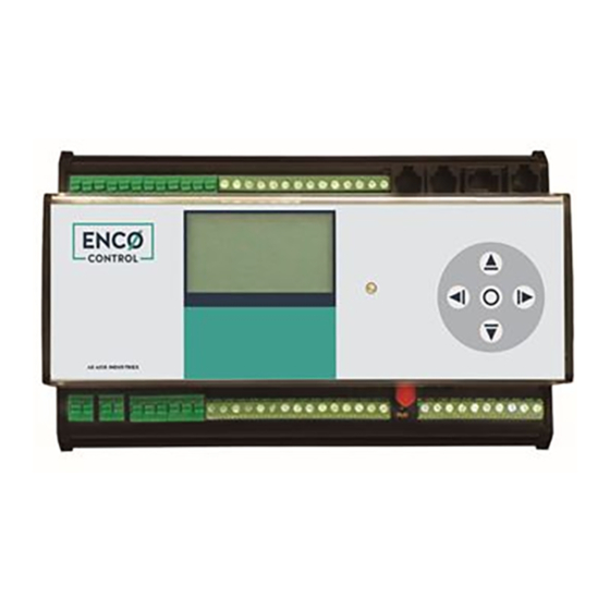
- Page 15 Caution: If this equipment is used in a manner not specified by the manufacturer, the protection provided by the equipment may be impaired. Fig. 11. Device Enco Control general view Fig. 12. Device Enco Control. Top view •...
- Page 16 ENCO Control Technical description Numbering of terminals GPRS modem • • • • • Kulautuvos g. 45a , LT-47190 Kaunas Tel. (+370 37) 360234 Faks. (+370 37) 360358 info@axis.lt www.axis.lt...
- Page 17 ENCO Control Technical description Table 11. Numbering of terminals Terminal Marking Permissible line Description number length, m Input Mains power supply 230V АС, L1 230V , Mains power supply 230V АС, Neutral 100mA Max Protective earthling Battery 12 V Battery (-) <= 3 m...
-
Page 18: Examples Of Wiring Diagrams
ENCO Control Technical description 30V max., 10 mA. Max. <= 20 m Analog input Analog input 4 (0-3V), Rin 10 kOhm <= 3 m <= 3 m 0-3V Ground <= 10 m Discrete input Discrete input 4 (0-3V) Rin 100 R <= 3 m... - Page 19 ENCO Control Technical description Enco Control PSU 230V DIN0 DIN1 DIN2 DIN3 Power is supplied from the external DC voltage 24 V б) Enco Control PSU 230V DIN0 DIN1 DIN2 DIN3 PSU 24 VDC • • • • • Kulautuvos g. 45a , LT-47190 Kaunas Tel.
- Page 20 ENCO Control Technical description Analog input wiring diagram DIN6 DIN5 DIN4 AIN4 PSU 230V Enco Control M-BUS device connection M-BUS M-BUS device device PSU 230V Enco Control Pressure sensors wiring diagram (4 sensors, 4-20 мА) PSU 230V Enco Control •...
- Page 21 ENCO Control Technical description Power control output connection ~230 L ~230 N Out 0 Out 1 Out 2 Out 3 Out 4 Out 5 Enco Control Out 6 Out 7 Out 8 • • • • • Kulautuvos g. 45a , LT-47190 Kaunas Tel.
- Page 22 ENCO Control Technical description Wiring diagram for connecting of the temperature sensors and RFID antennas RF ID T sensor ... . • • • • • Kulautuvos g. 45a , LT-47190 Kaunas Tel.
- Page 23 ENCO Control Technical description Serial communication interface connectors and expansion connector Fig. 19. Table 12. Numbering of terminals Terminal Description number Serial interface connector J28 (type RJ11) J28.1 Port 1, signal TX (RS232) J28.2 Port 1, GND J28.3 Port 1, signal RX (RS232) J28.4...
- Page 24 ENCO Control Technical description Enco Control into the cabinet with the opened first transparent door. • • • • • Kulautuvos g. 45a , LT-47190 Kaunas Tel. (+370 37) 360234 Faks. (+370 37) 360358 info@axis.lt www.axis.lt...
- Page 25 ENCO Control Technical description AB "Axis Industries" Kulautuvos g. 45a LT-47190 Kaunas, Lithuania Tel. (+370 37) 36 02 34 Faks. (+370 37) 36 03 58 info@axis.lt • • • • • Kulautuvos g. 45a , LT-47190 Kaunas Tel. (+370 37) 360234 Faks.
Need help?
Do you have a question about the Control and is the answer not in the manual?
Questions and answers