
Related Manuals for GE GEH6.0-3U-20


Summary of Contents for GE GEH6.0-3U-20
- Page 1 6.0-15kW G2 Three Phase User Manual V1.0 Hybrid Inverter www.gesolarinverter.com...
- Page 2 User Manual V1.0-2023-10-30 CONTENT Trademarks and other GE trademarks are trademarks of General Electric Company. All other trademarks or registered trademarks mentioned in this manual are owned by General Electric Company. Notice The information in this user manual is subject to change due to product updates or other reasons. This guide cannot replace the product labels or the safety precautions in the user manual unless otherwise specified.
-
Page 3: Table Of Contents
CONTENT User Manual V1.0-2023-10-30 CONTENT About This Manual ..................1 1.1 Applicable Model ........................1 1.2 Target Audience ........................1 1.3 Symbol Definition ........................1 Safety Precaution ................... 2 2.1 General Safety ..........................2 2.2 DC Side Safety .........................2 2.3 AC Side Safety ..........................3 2.4 Inverter Safety ..........................3 2.5 Battery Safety ...........................4 2.6 Personnel Requirements ......................4... - Page 4 User Manual V1.0-2023-10-30 CONTENT 6.5 Connecting the DC Input Cable(PV) ..................38 6.6 Connecting the Battery Cable ....................40 6.7 Connecting the AC Cable ....................... 42 6.8 Communication Connection ....................45 6.8.1 Connecting the Communication Cable ....................50 6.8.2 Connecting the CT ...........................53 6.8.3 Parallel system DIP switch........................54 6.9 Installing the Communication Module (Optional) ..............
-
Page 5: About This Manual
All the installers and users have to be familiar with the product features, functions, and safety precautions. This manual is subject to update without notice. For more product details and latest documents, visit www.gesolarinverter.com. 1.1 Applicable Model This manual applies to the listed hybrid inverters below: • GEH6.0-3U-20 • GEH8.0-3U-20 • GEH9.9-3U-20 • GEH10-3U-20 •... -
Page 6: Safety Precaution
Safety Precaution User Manual V1.0-2023-10-30 Safety Precaution Please strictly follow these safety instructions in the user manual during the operation. NOTICE The inverters are designed and tested to strictly comply with related safety rules. Read and follow all the safety instructions and cautions before any operations. Improper operation might cause personal injury or property damage as the inverters are electrical equipment. -
Page 7: Ac Side Safety
Safety Precaution User Manual V1.0-2023-10-30 2.3 AC Side Safety WARNING • The voltage and frequency at the connecting point should meet the on-grid requirements. • Additional protective devices like circuit breakers or fuses are recommended on the AC side. Specification of the protective device should be at least 1.25 times the rated AC output rated current. -
Page 8: Battery Safety
Safety Precaution User Manual V1.0-2023-10-30 2.5 Battery Safety WARNING • The battery used with the inverter shall be approved by the inverter manufacturer. The approved battery list can be obtained through the official website. • Before installations, read through the corresponding battery's user manual to learn about the product and the precautions. -
Page 9: Product Introduction
Note: GEH9.9-3U-20 is only available in the Australia. Model GEH6.0-3U-20 1 2 3 Referring to Explanation Brand Code GE: General Electric Equipment Type H: Equipment Type Rated Power 6.0: the rated power is 6kW. 8.0: the rated power is 8kW. 9.9: the rated power is 9.9kW. -
Page 10: Application Scenarios
Product Introduction User Manual V1.0-2023-10-30 Supported Grid Types For the grid type with neutral wire, the voltage between the neutral wire and the ground must be less than 10V. TN-S TN-C TN-C-S Inverter Inverter Inverter Inverter 3.2 Application Scenarios WARNING •... - Page 11 • Recommended specifications of AC circuit breaker: • For GEH6.0-3U-20: the nominal current is ≥ 20A and the nominal voltage is ≥ 230V AC. • For GEH8.0-3U-20: the nominal current is ≥ 25A and the nominal voltage is ≥ 230V AC.
- Page 12 • Recommended specifications of AC Circuit Breaker and SPDT Switch: • For GEH6.0-3U-20: the nominal current is ≥ 20A and the nominal voltage is ≥ 230V AC. • For GEH8.0-3U-20: the nominal current is ≥ 25A and the nominal voltage is ≥...
- Page 13 Product Introduction User Manual V1.0-2023-10-30 Multiple Inverters Parallel Scheme WARNING • Off grid multiple inverters parallel system is not supported. Do not parallel the BACK-UP ports of each inverter in the system. • When installing a parallel system, please consider factors such as a communication cable length of 2m, and plan the installation distance of the equipment reasonably.
- Page 14 Product Introduction User Manual V1.0-2023-10-30 RS485 PV string Master Inverter Ensure that the position ON-GRID circuit and direction of the breaker electricity meter and Battery 1 CT are correct. Battery Smart SPDT breaker meter BACK-UP load Ezlink Module (Single breaker Pole, Double Throw)
- Page 15 2 horsepower DC switch. • Recommended specifications: • For GEH6.0-3U-20 and GEH8.0-3U-20: the nominal current is ≥ 40A and the nominal voltage is ≥ 720V DC. • Other models: the nominal current is ≥ 50A and the nominal voltage is ≥...
- Page 16 AC circuit breakers shall be prepared by the breaker customers, and the recommended specifications: • For GEH6.0-3U-20: the nominal current is ≥ 20A and the nominal voltage is ≥ 230V AC. • Other models: the nominal current is ≥ 32A and the nominal voltage is ≥...
- Page 17 Product Introduction User Manual V1.0-2023-10-30 Parts Description Switchboard • Switchboard shall be prepared by the customers. • The rated current of the switchboard is ≥ 2 x N x IMax (N: number of inverters in the parallel system; IMax: maximum output current of the inverter).
-
Page 18: Working Mode
Product Introduction User Manual V1.0-2023-10-30 3.3 Working Mode 3.3.1 System Working Mode Self Consumption Mode NOTICE • For solar power, consider self consumption mode in priority: the excess power charges the battery in day time; the battery supplies power to the load when there is no solar power generated at night. - Page 19 Product Introduction User Manual V1.0-2023-10-30 Economic Mode NOTICE • Economic mode can only be selected if local laws and regulations are met, such as whether to allow the power grid to charge the battery and whether to allow the battery to be discharged and sold to the power grid.
- Page 20 Product Introduction User Manual V1.0-2023-10-30 Delayed Charging Mode NOTICE • Delayed charging mode can prevent the battery from quickly filling up and wasting energy when the PV energy exceeds the limit power value. • It applies to regions with grid connected power output limitations. •...
- Page 21 Product Introduction User Manual V1.0-2023-10-30 BACK-UP Mode NOTICE • In BACK-UP mode, you can set different battery SOC values for grid-tied and off-grid status. When the power grid is cut off, the inverter switches to off-grid mode, and the battery can dis- charge to supply power to the load to ensure that the BACK-UP load does not lose power;...
-
Page 22: Inverter Operation Mode
Product Introduction User Manual V1.0-2023-10-30 3.3.2 Inverter Operation Mode Waiting mode Off-grid mode Self-check mode Grid-connected Fault mode mode Parts Description Waiting The state when the equipment is in the waiting stage after being powered on or mode when the power grid is normal and the off grid output function is enabled, and the off grid output terminal is powered by the power grid. -
Page 23: Features
Product Introduction User Manual V1.0-2023-10-30 3.4 Features Power derating In order to ensure the safe operation of the inverter and meet local safety regulations, the inverter will automatically reduce the output power when the operating environment is not ideal. The following are the factors that may occur power derating. Please try to avoid them when the inverter is working. - Page 24 Product Introduction User Manual V1.0-2023-10-30 Model Description GEH6.0-3U-20 F-I-AFPE-1-2-1 F: Full coverage I: Integrated AFPE: Detection and interruption capability provided 1: 1 monitored string per input port GEH8.0-3U-20 2: 2 input ports per channel 1: 1 monitored channel GEH9.9-3U-20 F-I-AFPE-1-2/ 1- 2...
- Page 25 Product Introduction User Manual V1.0-2023-10-30 Load Control The inverter reserves a dry contact controlling port, which supports connecting SG Ready certified heat pumps and controllable loads for controlling load on or off. The load control methods are as follows: • Time control: In standard time mode, the time for controlling the load to turn on or off can be set, and the load will automatically turn on or off within the set time period;...
-
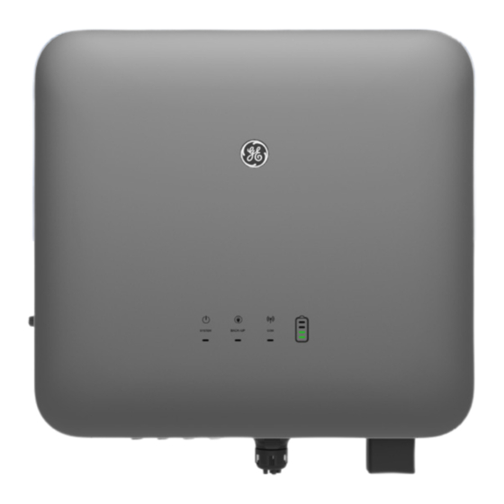
Page 26: Appearance
DC switch Control DC input connection or disconnection. Breather valve PV input terminal Connect the PV module DC input cables. • GEH6.0-3U-20/GEH8.0-3U-20: MPPT x 2 • GEH9.9-3U-20, GEH10-3U-20, GEH12-3U-20, GEH15-3U-20: MPPT x 3 Battery DC input/ Connect the battery input cables. -
Page 27: Dimension
Product Introduction User Manual V1.0-2023-10-30 3.5.2 Dimension 3.5.3 Indicator Description Inverter indicator Indicator Status Description The inverter is powered on and in standby mode. The inverter is starting and in self-check mode. The inverter is in normal operation under grid-tied or off-grid modes. SYSTEM BACK- UP output overload. -
Page 28: Nameplate
25% and 50%, the light at the 50% position blinks. 3.5.4 Nameplate The nameplate is for reference only. Product: Hybrid Inverter Model : GEH**-***-** GE trademark, product type, and product model DCmax: ***Vd.c. MPP: **... Vd.c. PV Input DC,max: **Ad.c. -
Page 29: Check And Storage
Check and Storage User Manual V1.0-2023-10-30 Check and Storage 4.1 Check Before Receiving Check the following items before receiving the product. 1. Check the outer packing box for damage, such as holes, cracks, deformation, and other signs of equipment damage. Do not unpack the contents from the box and contact the supplier as soon as possible if any damage is found. -
Page 30: Storage
Check and Storage User Manual V1.0-2023-10-30 Deliverables for parallel system(Ezlink module) NOTICE By default, 5 communication cables will be distributed, each with a length of 2m. Ezlink module Communication cable x 5 4.3 Storage If the equipment is not to be installed or used immediately, please ensure that the storage environment meets the following requirements: 1. -
Page 31: Installation
Installation User Manual V1.0-2023-10-30 5 Installation 5.1 Installation Requirements Installation Environment Requirements 1. Do not install the equipment in a place near flammable, explosive, or corrosive materials. 2. Do not install the equipment in a place that is easy to touch, especially within children’s reach. High temperature exists when the equipment is working. - Page 32 05 Installation User Manual V1.0-2023-10-30 Children No Touch ≥300mm ≥200mm ≥200mm ≥300mm ≥500mm ALT: 4000m IP66 0%~100%RH...
- Page 33 Installation User Manual V1.0-2023-10-30 Mounting Support Requirements • The mounting support shall be nonflammable and fireproof. • Install the equipment on a surface that is solid enough to bear the inverter weight. • Do not install the product on the support with poor sound insulation to avoid the noise bothering people nearby.
- Page 34 05 Installation User Manual V1.0-2023-10-30 Installation Tool Requirements The following tools are recommended when installing the equipment. Use other auxiliary tools on site if necessary. RJ45 crimping Goggles Safety shoes Safety gloves Dust mask tool Diagonal pliers Wire stripper Hammer drill Heat gun Vacuum cleaner Marker...
-
Page 35: Inverter Installation
Installation User Manual V1.0-2023-10-30 5.2 Inverter Installation 5.2.1 Moving the Inverter CAUTION • Operations such as transportation, shipment, installation and so on shall in compliance with the laws and regulations of the country or region where the inverter is located. •... - Page 36 05 Installation User Manual V1.0-2023-10-30 Aperture: 8mm Hole depth: 80mm 3N·m Only for Australia 1.2~2N·m...
-
Page 37: Electrical Connection
Electrical Connection User Manual V1.0-2023-10-30 Electrical Connection 6.1 Safety Precaution DANGER • Perform electrical connections in compliance with local laws and regulations. Including operations, cables, and component specifications. • Disconnect the DC switch and the AC output switch of the inverter to power off the inverter before any electrical connections. - Page 38 Electrical Connection User Manual V1.0-2023-10-30 Cable Requirements Specifications Battery CAN Please use the BMS commu- communication nication cable shipped in the Cable length: 3m cable attachment. • Please use the BMS com- munication cable shipped in the attachment.. • If the length of the com- munication cable shipped with the box cannot meet (Optional)
-
Page 39: Wiring Diagram
Electrical Connection User Manual V1.0-2023-10-30 6.3 Wiring Diagram NOTICE • N and PE wiring via ON-GRID and BACK-UP ports of the inverter are different based on the regulation requirements of different regions. Refer to the specific requirements of local regulations. •... - Page 40 Electrical Connection User Manual V1.0-2023-10-30 N and PE cables of BACK-UP load end shall be wired separately in the distribution box. Other countries except Australia, New Zealand, etc., are applicable to the following wirings. NOTICE If the inverter switches to off grid mode without connecting N and PE cables, the "Back-up N and PE relay switch"...
-
Page 41: Connecting The Pe Cable
Electrical Connection User Manual V1.0-2023-10-30 6.4 Connecting the PE cable WARNING • The PE cable connected to the enclosure of the inverter cannot replace the PE cable connected to the AC output port. Make sure that both of the two PE cables are securely connected. •... -
Page 42: Connecting The Dc Input Cable(Pv)
Electrical Connection User Manual V1.0-2023-10-30 6.5 Connecting the DC Input Cable(PV) DANGER • Do not connect one PV string to more than one inverter at the same time. Otherwise, it may cause damage to the inverter. • The PV strings cannot be grounded. Ensure the minimum insulation resistance of the PV string to the ground meets the minimum insulation impedance requirements before connecting the PV string to the inverter (R=maximum input voltage/ 30mA). - Page 43 Electrical Connection User Manual V1.0-2023-10-30 7~8mm Φ: 4~5mm 7~8mm Copper, 4mm ≤S≤6mm Click YQK-70 Click ≤1000V...
-
Page 44: Connecting The Battery Cable
Electrical Connection User Manual V1.0-2023-10-30 6.6 Connecting the Battery Cable DANGER • The battery used with the inverter shall be approved by the inverter manufacturer. The approved battery list can be obtained through the official website. • The positive and negative poles of the battery cannot be grounded. Before connecting the battery to the inverter, please ensure that the minimum insulation resistance to ground of the battery meets the minimum insulation impedance requirement (R=maximum input voltage/30mA). - Page 45 Electrical Connection User Manual V1.0-2023-10-30 Vaconn Connector Click 7~8mm Φ:5~8.5mm 7~8mm Copper, 8mm ≤S≤13.5mm Click YQK-70 Click ≤ 720V...
-
Page 46: Connecting The Ac Cable
DC component of the leakage current exceeds the limit value. The following RCDs are for reference: Inverter Model RCD Type (ON-GRID) RCD Type (BACK-UP) GEH6.0-3U-20 GEH8.0-3U-20 GEH9.9-3U-20 300mA 30mA... - Page 47 Electrical Connection User Manual V1.0-2023-10-30 Type I L=l+2mm Φ: 18mm BACK-UP:75mm ON-GRID:55mm Copper wire, S=6mm Click...
- Page 48 Electrical Connection User Manual V1.0-2023-10-30 Type II L=l+2mm BACK-UP:75mm ON-GRID:55mm Copper wire, S=6mm Click...
-
Page 49: Communication Connection
Electrical Connection User Manual V1.0-2023-10-30 If you need to remove the protection cover, please refer to the following steps. Step1: Use an external hexagonal screwdriver to press the unlock hole to unlock the protection cover. Step2: Remove screwdriver. Step3: Remove the protection cover. Type I Type II 6.8 Communication Connection... - Page 50 Electrical Connection User Manual V1.0-2023-10-30 Function Port Definition Function Description • CAN and BUS ports: parallel com- munication ports, and use CAN 1.Orange&White: RS485A communication to connect other 2.Orange: RS485B inverters in the parallel system; (Optional) Parallel 3.Green and White: - Use BUS to control the on-grid and communication port, 4.Blue: CANH...
- Page 51 Electrical Connection User Manual V1.0-2023-10-30 Function Port Definition Function Description • Support access to generator con- (Optional) Generator trol signals. control port (GEN) • Do not connect the generator pow- er cable to the inverter AC port. DRM0 or REF_1 •...
- Page 52 Electrical Connection User Manual V1.0-2023-10-30 16 COM/DRM0 or REF_1 17 REFGEN or REF_2 18 DRM4/8 or DI_4 19 DRM3/ 7 or DI_3 20 DRM2/6 or DI_2 100% 21 DRM1/5 or DI_1 Inverter Load monitoring and output power limitation networking The inverter can monitor the load electricity consumption in real-time and control the inverter's real- time output power through the connection of CT.
- Page 53 Electrical Connection User Manual V1.0-2023-10-30 Load monitoring and output power limitation networking (GM3000 or GM330) When the connection distance between the inverter and CT exceeds 20m, the data acquisition accuracy may decrease. An external GM3000 or GM330 meter can be connected for higher precision monitoring of load electricity consumption and real-time output power control of the inverter.
-
Page 54: Connecting The Communication Cable
Electrical Connection User Manual V1.0-2023-10-30 6.8.1 Connecting the Communication Cable NOTICE • When using built-in meters for networking in a parallel system, only the master inverter needs to connect CT cable. • Please use the CT connection cable shipped in the attachment. •... - Page 55 Electrical Connection User Manual V1.0-2023-10-30 Φ: 5-8mm 50mm 0.2mm ≤ S ≤ 0.4mm...
- Page 56 Electrical Connection User Manual V1.0-2023-10-30 PAR- PAR-1&EMS485 PAR-2 1&EMS485 PAR-2 LOAD CNTL 9: DO+ 10: DO- 4. Blue&White: CANH 11: DO+ 1: CT1+ 5. Blue&White: CANL PAR-1&EMS485 12: DO- 2: CT1- Meter Other: - 1. Orange&White: RS485A 3: CT2+ DRED/RCR DRED/RCR 19: RS485B 2.
-
Page 57: Connecting The Ct
Electrical Connection User Manual V1.0-2023-10-30 6.8.2 Connecting the CT NOTICE • Please use the CT connection cable shipped in the attachment. • When using only the built-in meter of the inverter, a CT communication cable needs to be con- nected. •... -
Page 58: Parallel System Dip Switch
Electrical Connection User Manual V1.0-2023-10-30 6.8.3 Parallel system DIP switch NOTICE • After the wiring of the parallel system is completed, the DIP switch of the first and last inverters needs to be turned to the ON position, and other inverters need to be turned to the 1 position. •... -
Page 59: Equipment Commissioning
Equipment Commissioning User Manual V1.0-2023-10-30 Equipment Commissioning 7.1 Check Before Power ON Check Item The product is firmly installed at a clean place that is well-ventilated and easy-to operate. The PE, DC input, AC output, and communication cables are connected correctly and securely. - Page 60 Equipment Commissioning User Manual V1.0-2023-10-30 Multiple inverters parallel system ON-GRID AC circuit breaker Master PV String Inverter Battery BACK-UP AC Battery circuit breaker breaker ON-GRID AC circuit breaker Slave PV String Inverter 1 Utility Utility meter grid Battery Battery BACK-UP AC circuit breaker breaker ON-GRID AC circuit breaker Slave...
-
Page 61: System Commissioning
System Commissioning User Manual V1.0-2023-10-30 System Commissioning 8.1 Indicators and Buttons Inverter Indicator Indicator Status Description The inverter is power on and in the standby mode. The inverter is starting and in self-check mode. The inverter is in normal operation under grid-tied or off-grid modes. SYSTEM BACK- UP output overload. -
Page 62: Setting Inverter Parameters Via We Mate App
System Commissioning User Manual V1.0-2023-10-30 8.2 Setting Inverter Parameters via WE Mate App NOTICE Please set the inverter parameters first via WE Mate App to ensure its operation. WE Mate App is a smart phone application used to communicate with the inverter via bluetooth, WiFi, 4G or 4G modules. - Page 63 System Commissioning User Manual V1.0-2023-10-30 Step1: Login parallel system After connecting the master inverter to the EzLink module, select the signal CCM-BLE * * * (* represents the last 8 digits of the inverter serial number). Step2: Set and adjust the parameters of parallel system according to the interface prompts and actual application scenarios.
- Page 64 System Commissioning User Manual V1.0-2023-10-30 Select the national safety regulations based on the actual situation. Select whether the inverter is connected to the battery. The number of inverters in parallel system can be auto- matically identified. If there is an error in the quantity, it can be manually corrected.
- Page 65 System Commissioning User Manual V1.0-2023-10-30 Step3: In parallel system, if the battery models connected to a single inverter are different, they can be set separately. Select whether the inverter is connected to the battery. Initial password: solar2019...
-
Page 66: Monitoring Via Power Sight
System Commissioning User Manual V1.0-2023-10-30 Select the actual battery model connected to the system. 8.3 Monitoring via Power Sight NOTICE In parallel system, only the master inverter needs to be added to the Power Sight monitoring plat- form, which can obtain all inverter information from the parallel system. If the slave inverter is added to the Power Sight monitoring platform, it will result in duplicate or distorted data in the parallel system. -
Page 67: Maintenance
Maintenance User Manual V1.0-2023-10-30 Maintenance 9.1 Power OFF the Inverter DANGER INSTRUCTIONS PERTAINING TO A RISK OF FIRE OR ELECTRIC SHOCK. • Power off the inverter before operations and maintenance. Otherwise, the inverter may be damaged or electric shocks may occur. •... -
Page 68: Removing The Inverter
Maintenance User Manual V1.0-2023-10-30 Multiple inverters parallel system ON-GRID AC circuit breaker Master PV String Inverter Battery Battery breaker BACK-UP AC circuit breaker ON-GRID AC circuit breaker Slave PV String Inverter 1 Utility meter Utility grid Battery Battery breaker BACK-UP AC circuit breaker ON-GRID AC circuit breaker PV String Slave... -
Page 69: Disposing Of The Inverter
Maintenance User Manual V1.0-2023-10-30 9.3 Disposing of the Inverter If the inverter cannot work anymore, dispose of it according to the local disposal requirements for electrical equipment waste. The inverter cannot be disposed of together with household waste. 9.4 Troubleshooting Perform troubleshooting according to the following methods. - Page 70 Maintenance User Manual V1.0-2023-10-30 Single inverter system Fault Cause Solutions PV power low 1. If it occurs accidentally, it may be due to abnormal lighting, and the inverter will PV voltage Low automatically resume normal operation Weak or abnormal without manual intervention. changes in lighting 2.
- Page 71 Maintenance User Manual V1.0-2023-10-30 Fault Cause Solutions 1. Excessive power 1. Confirm whether the connected load power is of connected load within the rated range of the equipment. 2. Insufficient Back-up Output 2. Confirm if there is insufficient light or battery energy on the DC AC Undervoltage power.
- Page 72 Maintenance User Manual V1.0-2023-10-30 Fault Cause Solutions 1. Improve the lightning protection facilities around the inverter; 2. You can determine whether it is necessary to contact the dealer/after-sales service center to handle DC side lightning protection device faults based on needs; DC side lightning 3.
- Page 73 Maintenance User Manual V1.0-2023-10-30 Fault Cause Solutions 1. If the problem occurs occasionally, the utility grid may be abnormal temporarily. The inverter will recover automatically after detecting that the utility grid is normal. 2. If the problem occurs frequently, check whether the grid voltage is within the allowed The grid voltage is range.
- Page 74 Maintenance User Manual V1.0-2023-10-30 Fault Cause Solutions 1. If the problem occurs occasionally, the utility grid may be abnormal temporarily. The inverter will recover automatically after detecting that the utility grid is normal. 2. If the problem occurs frequently, check The moving average whether the grid voltage is within the allowed of grid voltage in...
- Page 75 Maintenance User Manual V1.0-2023-10-30 Fault Cause Solutions 1. If the problem occurs occasionally, the utility grid may be abnormal temporarily. The inverter will recover automatically after detecting that the utility grid is normal. 2. If the problem occurs frequently, check whether the grid frequency is within the Utility grid exception.
- Page 76 Maintenance User Manual V1.0-2023-10-30 Fault Cause Solutions Utility grid exception. 1. If the problem occurs occasionally, the The duration of the LVRT utility grid may be abnormal temporarily. utility grid exception Undervoltage The inverter will recover automatically after exceeds the set time detecting that the utility grid is normal.
- Page 77 Maintenance User Manual V1.0-2023-10-30 Fault Cause Solutions 1. The PV voltage is too high. Disconnect the AC output switch and DC input 2. The sampling switch, then connect them 5 minutes later. BUS Overvoltage of the inverter Contact the dealer or the after-sales service if BUS voltage is the problem persists.
- Page 78 Maintenance User Manual V1.0-2023-10-30 Fault Cause Solutions 1. If it occurs accidentally, it may be due to 1. Abnormal load abnormal lighting, and the inverter will BUS Voltage access automatically resume normal operation Imbalance 2. Hardware without manual intervention. problem 2.
-
Page 79: Routine Maintenance
Maintenance User Manual V1.0-2023-10-30 Fault Cause Solutions Possible cause of external fan abnormal: 1.The power Disconnect the AC output switch and DC input External fan supply to the fan is switch, then connect them 5 minutes later. abnormal abnormal; Contact the dealer or the after-sales service if 2.Mechanical failure the problem persists. -
Page 80: Technical Parameters
Technical Parameters User Manual V1.0-2023-10-30 Technical Parameters Technical parameters GEH6.0-3U-20 GEH8.0-3U-20 GEH9.9-3U-20 Battery Input Data Battery Type Li-Ion Li-Ion Li-Ion Nominal Battery Voltage (V) Battery Voltage Range (V) 150~720 150~720 150~720 Start-up Voltage (V) Number of Battery Input Max. Continuous Charging Current (A) Max. - Page 81 Technical Parameters User Manual V1.0-2023-10-30 Technical parameters GEH6.0-3U-20 GEH8.0-3U-20 GEH9.9-3U-20 Max. Apparent Power from Utility 12,000 16,000 20,000 Grid (VA) Nominal Output Voltage (V) 400/380, 3L/N/PE 400/380, 3L/N/PE 400/380, 3L/N/PE Output Voltage Range (V)* 170~290 170~290 170~290 Nominal AC Grid Frequency (Hz)
- Page 82 Technical Parameters User Manual V1.0-2023-10-30 Technical parameters GEH6.0-3U-20 GEH8.0-3U-20 GEH9.9-3U-20 Efficiency Max. Efficiency 98.0% 98.0% 98.2% European Efficiency 97.2% 97.2% 97.5% Max. Battery to AC Efficiency 97.2% 97.5% 97.5% MPPT Efficiency 99.5% 99.5% 99.5% Protection PV Insulation Resistance Integrated Integrated...
- Page 83 Technical Parameters User Manual V1.0-2023-10-30 Technical parameters GEH6.0-3U-20 GEH8.0-3U-20 GEH9.9-3U-20 Noise Emission (dB) <30 <30 <30 Topology Non-isolated Non-isolated Non-isolated Self-consumption at Night (W)* <15 <15 <15 Ingress Protection Rating IP66 IP66 IP66 DC Connector MC4 (4~6mm MC4 (4~6mm MC4 (4~6mm...
- Page 84 Technical Parameters User Manual V1.0-2023-10-30 Technical parameters GEH10-3U-20 GEH12-3U-20 GEH15-3U-20 Battery Input Data Battery Type Li-Ion Li-Ion Li-Ion Nominal Battery Voltage (V) Battery Voltage Range (V) 150~720 150~720 150~720 Start-up Voltage (V) Number of Battery Input Max. Continuous Charging Current Max.
- Page 85 Technical Parameters User Manual V1.0-2023-10-30 Technical parameters GEH10-3U-20 GEH12-3U-20 GEH15-3U-20 Nominal Output Voltage (V) 400/380, 3L/N/PE 400/380, 3L/N/PE 400/380, 3L/N/PE Output Voltage Range (V)* 170~290 170~290 170~290 Nominal AC Grid Frequency (Hz) 50/60 50/60 50/60 AC Grid Frequency Range (Hz) 45~65 45~65 45~65...
- Page 86 Technical Parameters User Manual V1.0-2023-10-30 Technical parameters GEH10-3U-20 GEH12-3U-20 GEH15-3U-20 Efficiency Max. Efficiency 98.2% 98.2% 98.2% European Efficiency 97.5% 97.5% 97.5% Max. Battery to AC Efficiency 97.5% 97.5% 97.5% MPPT Efficiency 99.5% 99.5% 99.5% Protection PV Insulation Resistance Detection Integrated Integrated Integrated PV AFCI3.0...
- Page 87 Technical Parameters User Manual V1.0-2023-10-30 Technical parameters GEH10-3U-20 GEH12-3U-20 GEH15-3U-20 Self-consumption at Night (W)* <15 <15 <15 Ingress Protection Rating IP66 IP66 IP66 DC Connector MC4 (4~6mm MC4 (4~6mm MC4 (4~6mm Feed-Through Feed-Through Feed-Through AC Connector Terminal Blocks Terminal Blocks Terminal Blocks UW10 UW10...
- Page 88 Global Sales & Service Network * GE is a registered trademark of General Electric Company and is used under license by GoodWe Technologies Co., Ltd. © 2023 All Rights Reserved No. 90 Zijin Rd., New District, Suzhou, 215011, China www.gesolarinverter.com sales@gesolarinverter.com;...
Need help?
Do you have a question about the GEH6.0-3U-20 and is the answer not in the manual?
Questions and answers