Advertisement
INSTALLATION AND MAINTENANCE INSTRUCTIONS
60-1039
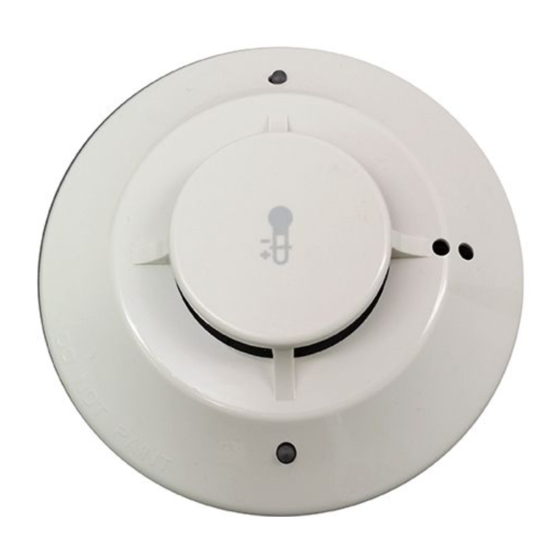
Intelligent Heat Detector
SPECIFICATIONS
Normal Operating Voltage:
Standby Current:
LED Current:
Operating Humidity Range:
Installation Temperatures:
Fixed Temperature Rating:
Rate of Rise Detection:
Height:
Diameter:
Weight:
BEFORE INSTALLING
This detector must be installed in compliance with the control panel system
installation manual. The installation must meet the requirements of the Au-
thority Having Jurisdiction (AHJ). Detectors offer maximum performance
when installed in compliance with the National Fire Protection Association
(NFPA); see NFPA 72.
PRODUCT DESCRIPTION
Model 60-1039 is an intelligent, spot-type heat detector, designed to be pro-
grammable for a setpoint range of 135ºF to 174ºF for ordinary detection or
175ºF to 190ºF for intermediate detection. Detectors in the ordinary range
may be programmed for either fixed or 15ºF rate of rise operation. Detectors
set between 135ºF to 155ºF or 175ºF to 190ºF are designed 50 foot spacing.
Detectors set between 156ºF to 174ºF are designed for 15 foot spacing. These
spacings are designated per UL 521.
The detector is designed with tri-color LEDs to indicate detector status. The
detector can be programmed to make the LEDs blink or be steady green, am-
ber, or red. The detector remote output can be configured to follow the LED
or be independently controlled. A remote LED annunciator is available as an
accessory (RA400Z/RA100Z).
WIRING GUIDE
All wiring must be installed in compliance with the National Electrical Code,
applicable local codes and the Authority Having Jurisdiction (AHJ). Proper
wire gauges should be used. The installation wires should be color coded to
limit wiring mistakes and ease system troubleshooting. Improper connections
will prevent a system from responding properly in the event of a fire.
1.
Wire the detector base (supplied separately) per the wiring diagram, see
Figure 1.
2.
Install the detector into the base. Push the detector into the base while
turning it clockwise to secure it in place.
3.
Set the desired address using the IR configuration tool (model no. EA-CT).
4.
Test the detector as described in the TESTING section of this manual.
FIGURE 1. WIRING DIAGRAM:
OPTIONAL REMOTE ANNUNCIATOR
(–)
(+)
(–)
(–)
(+)
OPTIONAL RETURN LOOP
D800-15-00
15 to 30 VDC
451 µA max. @ 24 VDC (continuous broadcasts)
2 mA max. @ 24 VDC (LEDs on)
10% to 93% Relative Humidity, Non-condensing
–4°F to 100°F (–20°C to 38°C), 135°F to 174ºF setpoint; –4°F to 150°F (–20°C to 66°C), 175°F to 190ºF setpoint
135°F to 190°F (57°C to 88°C); programmable
Responds to greater than 15°F/min.(8ºC/mm); programmable
2.1˝ (51 mm)
6.1˝ (155 mm) installed; 4.1˝ (104 mm) installed
4.8 ounces (137 g)
(+)
C0113-00
TAMPER RESISTANCE
The detector bases have a tamper-resistant capability. When this capability is
enabled, detector cannot be removed from the base without the use of a tool.
Refer to the detector base installation instruction manual for details in using
this capability.
TESTING
Before testing, notify the proper authorities that the system is undergoing
maintenance, and will temporarily be out of service. Disable the system to
prevent unwanted alarms.
The detector can be tested in the following ways:
A.
Functional:
This detector can be functionally tested by using the EA-CT. Following
the instructions, initiate the detector test sequence. The detector will
then send a test alarm message to the panel. Refer to the control panel
technical documentation for further information.
B.
Direct Heat:
A hair dryer, heat gun, or test apparatus designed for this purpose should
be used to test the sensing circuit. Direct the heat toward the thermistor,
using care to avoid damaging the plastic housing. The detector will reset
only after if has had sufficient time to cool.
Detectors that fail these tests should be cleaned as described under CLEAN-
ING and retested. If the detectors still fail these tests they should be returned
for repair.
CLEANING
NOTE: Before cleaning notify the proper authorities that the system is un-
dergoing maintenance, and therefore the system will temporarily be out of
service. Disable the loop or system undergoing maintenance to prevent un-
wanted alarms.
It is recommended that the detector be removed from its mounting base for
easier cleaning and that detectors be cleaned at least once a year. Use a vac-
uum cleaner to remove dust from the sensing chamber.
FIGURE 2:
1
704 S. 10th Street
Blue Springs, MO 64015
Phone: 816.229.3405; Fax: 816.228.9277
C010-00
I56-2466-006R
R
Advertisement
Table of Contents

Related Manuals for Fike 60-1039


Summary of Contents for Fike 60-1039
- Page 1 PRODUCT DESCRIPTION maintenance, and will temporarily be out of service. Disable the system to Model 60-1039 is an intelligent, spot-type heat detector, designed to be pro- prevent unwanted alarms. grammable for a setpoint range of 135ºF to 174ºF for ordinary detection or 175ºF to 190ºF for intermediate detection.
- Page 2 – Increase the separation between the equipment and receiver. – Connect the equipment into an outlet on a circuit different from that to which the receiver is connected. – Consult the dealer or an experienced radio/TV technician for help. D800-15-00 I56-2466-006R ©2012 Fike...
Need help?
Do you have a question about the 60-1039 and is the answer not in the manual?
Questions and answers