Federal Signal Corporation C Series Description, Specifications, Installation, And Operation Manual
Informer-pa for public address interface
Hide thumbs
Also See for C Series:
Table of Contents

Related Manuals for Federal Signal Corporation C Series


Summary of Contents for Federal Signal Corporation C Series
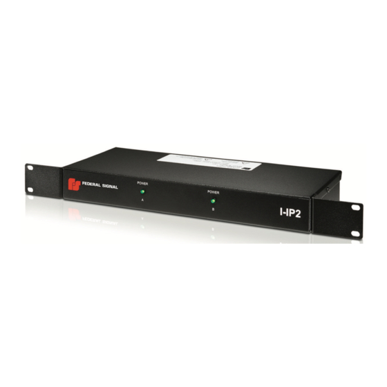
- Page 1 Informer-PA for Public Address Interface Model I-IP2 Series C Dual Rack/Wall Mount Description, Specifications, Installation, and Operation Manual 25500526 Rev. C0 0820 Printed in U.S.A. © Copyright 2019-2020 Federal Signal Corporation...
- Page 2 A copy of this limited warranty can also be obtained by written request to Federal Signal Corporation, 2645 Federal Signal Drive, University Park, IL 60484, email to info@fedsig.com or call +1 708-534-3400.
-
Page 3: Table Of Contents
Contents Safety Messages..............................5 Safety Messages to Installers ..........................5 General Description ..............................7 Introduction .................................7 Features ................................7 Ordering Information ............................8 Specifications ................................9 Installation ................................10 Determine a Suitable Location ..........................10 Rack Mounting ..............................10 Wall Mounting ..............................11 Memory Card Removal and Installation ......................12 Testing and Training ..............................13 Operations................................13 Input/Output Locations ............................13... - Page 4 Tables Table 1 Ordering Information ..........................8 Table 2 Optional Accessories ..........................8 Table 3 Specifications .............................9 Table 4 Compliance ..............................9 Table 5 Visual Indications .............................14 Table 6 JP3 Input/Output Connections ........................14 Table 7 J1 Rear Input .............................14 Table 8 FS232 Connector Pin-out ........................15 Table 9 J2 Input Power ............................15 Table 10 Replacement Part Numbers ........................16 Figures...
-
Page 5: Safety Messages
Safety Messages Safety Messages It is important to follow all instructions shipped with this product. This device is to be installed by trained personnel who are thoroughly familiar with the country electric codes and will follow these guidelines as well as local codes and ordinances, including any state or local noise control ordinances. - Page 6 Safety Messages • Any maintenance to the unit MUST be performed by a trained electrician in accordance with NEC Guidelines and local codes or a Federal Signal certified Service Provider. • Never alter the unit in any manner. • The nameplate should NOT be obscured, as it contains cautionary and/or other information of importance to maintenance personnel.
-
Page 7: General Description
General Description General Description Introduction The Informer-PA (model I-IP2) is part of the Federal Signal Intelligent Systems product line designed to interface in-building Public Address (PA) systems. An I-IP2 houses two Informer-PA PCBs each capable of driving one amplifier channel. Each Informer-PA is an independent device with a LAN interface, digital voice message storage, relays, alarm input, and audio out. -
Page 8: Ordering Information
General Description • LED status indicators for Power. • Ability to activate onboard relays to control external devices. • Informers are addressable Individually, in Groups, or All. • Requires minimal network bandwidth and uses TCP/IP protocol for security and reliability. •... -
Page 9: Specifications
Specifications Specifications Table 3 Specifications Operating Voltages 9-15 Vdc 108-128 Vac, 60 Hz with wall transformer Operating Current Standby (at 12 Vdc) ≤ 400 mA (from wall transformer for I-IP2) Signaling (at 12 Vdc) < 650 mA Operating with PoE, PoE: 48 Vdc (42 to 57 Vdc), IEEE 802.3af IEEE 802.3af, 48V input Standby (at 48 Vdc) <... -
Page 10: Installation
Installation Installation Read and adhere to all safety warnings in this manual before installing the Informer-PA. To prevent injury, this apparatus must be securely attached to the wall per the installation instructions. SHOCK HAZARD: Electrocution or severe personal injury can occur when making electrical connections, drilling holes, or lifting equipment. -
Page 11: Wall Mounting
Installation Figure 2 Rack Mount Dimensions 6.06" 14.18 0.41" 1.70" 1.25" 18.28 18.98 Connect each Informer-PA to the LAN using CAT5 cable. If the Wired Ethernet has PoE, no other power connection is required. If PoE is not available, run the supplied external AC/DC power supply against the wall and plugged into a 120 Vac, 60 Hz outlet. -
Page 12: Memory Card Removal And Installation
Installation Figure 4 Wall Mount Dimensions 14.18 1.71" 18.98 18.28 1.70" 1.25" 6.06" Connect the Informer-PA to the LAN using CAT5 cable. If the Wired Ethernet has PoE, no other power connection is required. If PoE is not available, run the supplied external AC/DC power supply against the wall and plugged into a 120 Vac, 60 Hz outlet. -
Page 13: Testing And Training
Testing and Training Testing and Training After the installation is complete, do the following: • Test the Informer-PA and all accessories from the control point(s) to ensure it is operating properly. • Ensure all users are properly trained to use the system before putting the Informer-PA into service. -
Page 14: Visual Indications
Operations Visual Indications Table 5 Visual Indications Description POWER The green Power LED turns on when power is connected and the device is connected to a Federal Signal enabled network server. The Power LED flashes on for 100 ms when the unit is disconnected from the server. Audio/Relay - Input/Output Connections The relays can be programmed to cycle on and off, or come on continuously with programmable on time, off time, and total-time. -
Page 15: Rs232 Port
Operations RS232 Port The RS232 Port uses a six-pin modular connector. Federal Signal can provide pre- terminated cables when scrolling message displays are purchased. Table 8 FS232 Connector Pin-out Description Serial / Flash Select CTS / Serial Clock In Ethernet Port The Informer-PA has an eight-pin Ethernet port for connecting to the Communications network. -
Page 16: Replacement Parts
Replacement Parts Replacement Parts The Informer-PA uses one of these two types of connectors: one with slots or one without slots. Match the eight-pin connector of your Informer to the picture below and order the corresponding part number. Table 10 Replacement Part Numbers Picture Part Number 13900406A-08...
Need help?
Do you have a question about the C Series and is the answer not in the manual?
Questions and answers