Federal Signal Corporation C Series Description, Specifications, Installation, And Operation Manual
Two-way ip-enabled intercom and alarm initiation point
Hide thumbs
Also See for C Series:
Table of Contents
Advertisement
Quick Links
Advertisement
Table of Contents

Related Manuals for Federal Signal Corporation C Series


Summary of Contents for Federal Signal Corporation C Series
- Page 1 Informer-IP Desk Mount Model I-IP-IO Series C Two-Way IP-enabled Intercom and Alarm Initiation Point Description, Specifications, Installation, and Operation Manual 25500524 Rev. C0 0820 Printed in U.S.A. © Copyright 2019-2020 Federal Signal Corporation...
- Page 2 A copy of this limited warranty can also be obtained by written request to Federal Signal Corporation, 2645 Federal Signal Drive, University Park, IL 60484, email to info@fedsig.com or call +1 708-534-3400.
-
Page 3: Table Of Contents
Contents Safety Messages..............................5 Safety Messages to Installers ..........................5 General Description ..............................8 Introduction ................................8 Features ................................8 Ordering Information ............................9 Specifications ................................10 Installation ................................11 Determine a Suitable Location ..........................12 Wall Mounting ..............................13 Desk Mounting ..............................13 Memory Card Removal and Installation ......................14 Testing and Training ............................14 Operations................................15 Controls ................................15... - Page 4 Tables Table 1 Ordering Information ..........................9 Table 2 Optional Accessories ..........................9 Table 3 Specifications ............................10 Table 4 Compliance ............................... 11 Table 5 Controls ..............................15 Table 6 Visual Indications (Located on keypad) ....................16 Table 7 JP3 Input/Output Connections ........................17 Table 8 J1 Rear Input .............................17 Table 9 FS232 Connector Pin-out ........................17 Table 10 J2 Input Power ............................18 Table 11 JP3 (on the main PCB) Microphone Enable Jumper ................18...
-
Page 5: Safety Messages
Safety Messages Safety Messages It is important to follow all instructions shipped with this product. This device is to be installed by trained personnel who are thoroughly familiar with the country electric codes and will follow these guidelines as well as local codes and ordinances, including any state or local noise control ordinances. - Page 6 Safety Messages • All effective warning sounds may, in certain circumstances, cause permanent hearing loss. Take appropriate precautions such as wearing hearing protection. Maximum sound level exposure limits specified in OSHA 29 CFR 1910 should not be exceeded. Review and comply with any local or state noise control ordinances as well as OSHA noise exposure regulations and guidelines.
- Page 7 Safety Messages Symbol Definition Indicates to reduce the risk of fire, replace fuse as marked. Pay careful attention to the notice located on the equipment. Read and understand the information contained in this manual before attempting to install or service the Informer. Description, Specifications, Installation, and Operation Manual Federal Signal www.fedsig.com...
-
Page 8: General Description
General Description General Description Introduction The Informer-IP Desk Mount is an intercom, a warning device, and an alarm initiation point that connects to an Ethernet network. An internal speaker is used to provide clear two-way voice communications between control and monitoring points and distributed locations. -
Page 9: Ordering Information
General Description • REPLAY button allows Alert messages to be replayed when the red Alert LED is flashing. • RESET button Silences Alerts. • Local and remote volume level controls. • Informers are addressable Individually, in Groups, or All. • Requires minimal network bandwidth and uses TCP/IP protocol for security and reliability. -
Page 10: Specifications
Specifications The following figure illustrates the wall mounted push buttons for activation. Figure 2 PS Series Push Button Stations (optional) Specifications Table 3 Specifications Operating Voltages at J2 9-15 Vdc using AC Transformer 108-128 Vac, 60 Hz with wall transformer Operating Current Standby: 9 V = <... -
Page 11: Installation
Installation Weight < 2.0 lb (0.9 kg) Shipping Weight 2.80 lb (1.27 kg) Table 4 Compliance Electromagnetic Complies with FCC Title 47, Part 15 Interference FCC Part 15 Radio Frequency Interference (RFI) (FCC 15.105) Class B The Informer-IP was tested and found to comply with the limits for Class B digital devices pursuant to Part 15 Subpart B of the FCC Rules. -
Page 12: Determine A Suitable Location
Installation Determine a Suitable Location When choosing a location for the Informer-IP, consider the following criteria: • Place as far as possible from electrically noisy electronic devices to avoid interference. Examples of noisy devices may include microwave ovens, motor-driven devices, light ballasts, and electrical switching devices. •... -
Page 13: Wall Mounting
Installation Wall Mounting Before mounting the unit, determine a suitable location considering the criteria listed. Located on the bottom of the unit, the Informer-IP has two keyholes that accept #8 screws. Place the mounting screws horizontally level, approximately 6 inches (15.2 cm) above eye level and 4 inches (10.16 cm) apart on center. -
Page 14: Memory Card Removal And Installation
Installation Memory Card Removal and Installation The microSD card stores voice and tone messages. To remove the card: Remove the top of the Informer. Find the microSD card. Gently push the card into the slot. The card can then be removed. To install the card: Insert and gently push the card until it latches into place. -
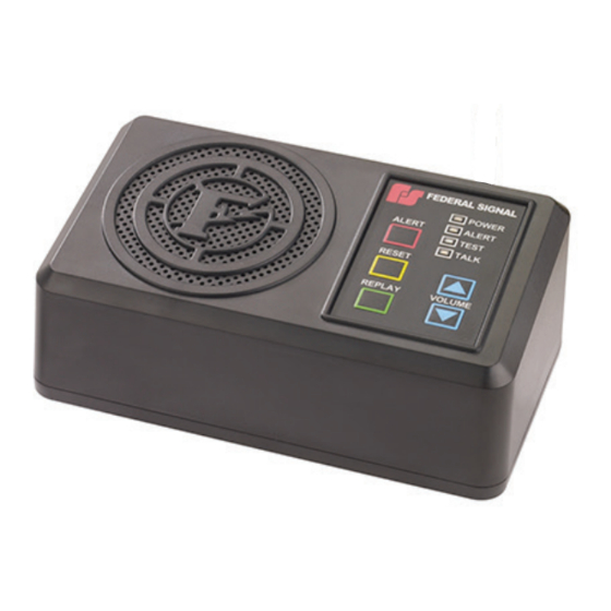
Page 15: Operations
Operations Operations The following is a picture of the Informer-IP keypad. Figure 4 Informer-IP Keypad Controls Table 5 Controls Button Description ALERT The ALERT button sends an activation to the control points and changes the status icon to Red. You can also configure inputs as a Call Request to alert emergency operations personnel that an intercom chat session is being requested. -
Page 16: Visual Indications
Operations Visual Indications Table 6 Visual Indications (Located on keypad) Description POWER The green Power LED turns on when power is connected and the device is connected to a Federal Signal enabled network server. The Power LED flashes on for 100 ms when the unit is disconnected from the server. ALERT The red Alert LED Flashes on and off at a 1/2 second interval when an alert is received. -
Page 17: Audio/Relay - Input/Output Connections
Operations Audio/Relay - Input/Output Connections The Informer-IP has two SPDT relays rated at 5 A at 30 Vdc. The relays can be programmed to cycle on and off, or come on continuously with programmable on time, off time, and total-time. The relay outputs can be reset manually or reset after a programmable number of seconds. -
Page 18: Ethernet Port
Operations Ethernet Port The Informer-IP has an eight-pin Ethernet port for connecting to the Communications network. The port accepts 42 to 57 Vdc PoE per IEEE 802.3af. (Early versions of the Informer-IP may require PoE Adapter 2005704A for proper PoE operation.) Ethernet wire runs must be less than 328 feet (100 meters) from the nearest network switch. -
Page 19: Replacement Parts
Replacement Parts Replacement Parts The Informer-IP uses one of these two types of connectors: one with slots or one without slots. Match the eight-pin connector of your Informer to the picture below and order the corresponding part number. Table 12 Replacement Part Numbers Picture Part Number 13900406A-08... - Page 20 2645 Federal Signal Drive University Park, Illinois 60484 www.fedsig.com Customer Support 800-548-7229 • +1 708 534-3400 Technical Support 800-524-3021 • +1 708 534-3400...
Need help?
Do you have a question about the C Series and is the answer not in the manual?
Questions and answers