GeoVision GV-SNVR0411 Quick Start Manual
Hide thumbs
Also See for GV-SNVR0411:
- User manual (90 pages) ,
- Quick start manual (54 pages) ,
- User manual (136 pages)
Table of Contents
Advertisement
Quick Links
Download this manual
See also:
User Manual
Advertisement
Table of Contents

Related Manuals for GeoVision GV-SNVR0411


Summary of Contents for GeoVision GV-SNVR0411
-
Page 1: Quick Start Guide
Quick Start Guide GV-SNVR System The Vision of Security Thank you for purchasing GV-SNVR. This guide is designed to assist the new user in getting immediate results from the GV-SNVR. For advanced information on how to use the GV-SNVR, please SNVR0411V210-QG-A refer to GV-SNVR User's Manual. - Page 2 Every effort has been made to ensure that the information in this manual is accurate. GeoVision, Inc. makes no expressed or implied warranty of any kind and assumes no responsibility for errors or omissions. No liability is assumed for incidental or consequential damages arising from the use of the information or products contained herein.
-
Page 3: Table Of Contents
1.1.2 Bundled Package for GV-SNVR0400F ............... 4 1.2 Compatible Products and System Requirements ............ 5 1.2.1 Supported GV-IP Cameras ..................5 1.2.2 Supported GeoVision Applications ................7 1.2.3 System Requirements ....................8 1.3 Options ........................8 2. Overview ......................9 Front View ...................... -
Page 4: Introduction
You can choose to purchase a GV-SNVR package or a bundled package which includes 4 GV-Target IP Camera of your choice and a GV-PoE switch. Package Options: Single Package for GV-SNVR0400F • Single Package for GV-SNVR0411 • Single Package for GV-SNVR1600 • Bundled Package for GV-SNVR0400F •... - Page 5 GV-SNVR0400F GV-SNVR0400F AC Power Cord AC/DC Adapter (DC 19V, 3.42A, 65 W) Screw x 6 (for HDD) SATA cable Firmware CD/DVD Software CD/DVD Quick Start Guide Warranty Card GV-SNVR1600 GV-SNVR1600 AC Power Cord SATA Cable x 4 HDD Mounting Bracket Kit (4 pairs and 32 screws included) Rack Mount (2 L-shaped brackets and 6 screws included)
-
Page 6: Bundled Package For Gv-Snvr0400F
1.1.2 Bundled Package for GV-SNVR0400F GV-SNVR400F Package x 1 Target IP Camera x 4 GV-POE0400 x 1 Note: For the Target IP Camera, select any 4 models from GV-EBL1100 / 2100, GV-EBX1100 / 2100, GV-EDR1100 / 2100, GV-EFD1100 / 2100. For more information, contact our sales representatives. -
Page 7: Compatible Products And System Requirements
1.2 Compatible Products and System Requirements 1.2.1 Supported GV-IP Cameras The GV-SNVR is compatible with the following GV-IP Cameras: ˙ GV-Target Series IP Cameras (Firmware V1.0 or later) ˙ GV-SD220/220-S (Firmware V1.04 or later) ˙ All the other GV-IP Cameras (Firmware V2.11 or later) EXCEPT the models below: GV-SNVR Firmware Not Supported Models System... - Page 8 IMPORTANT: 1. The GV-SNVR supports the recording frame rate of up to 30 fps only. 2. The GV-SNVR supports a total bandwidth of up to 40 Mbps for GV-SNVR0411, 50 Mbps for GV-SNVR0400F and 100 Mbps for GV-SNVR1600. GV-Fisheye Cameras, except GV-FER12203, are only supported on channel 1 of GV-SNVR1600 (*).
-
Page 9: Supported Geovision Applications
1.2.2 Supported GeoVision Applications The GV-SNVR is compatible with the following applications: For GV-SNVR0411 ˙ GV-Edge Recording Manager (Windows Version V1.2.0.0 or later) ˙ GV-Control Center (V3.4.0.0 or later) ˙ GV-Center V2 (V16.10 or later) ˙ GV-Vital Sign Monitor (V16.10 or later) ˙... -
Page 10: System Requirements
1.2.3 System Requirements Recommended Hard Disks GV-SNVR0411 supports 1 SATA HDD (3.5”) with up to 8 TB capacities, GV-SNVR0400F supports 1 SATA HDD (3.5”) with up to 4 TB capacities, and GV-SNVR1600 supports 4 SATA HDD (3.5”) with total up to 16 TB capacities. For system efficiency, it is recommended to use the enterprise-level hard disk drives instead of desktop-level or green HDD. -
Page 11: Overview
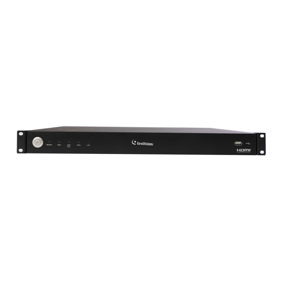
2. Overview Front View 2.1.1 GV-SNVR0411 No. Name Function Power LED Shows constant Green when the power is supplied for the device. Shows constant red when the following situations occur: ˙ No hard drive is installed. HDD Fail LED ˙ The hard drive is not formatted. -
Page 12: Gv-Snvr0400F
2.1.2 GV-SNVR0400F 1 2 3 No. Name Function USB 2.0 Port Connects to keyboard, mouse, USB flash drive or GV-Joystick V2. Audio In Not functional. Audio Out Connects to speaker. Power LED Shows constant blue when the power is supplied for the device. Shows constant red when the following situations occur: ˙... -
Page 13: Gv-Snvr1600
2.1.3 GV-SNVR1600 No. Name Function Power Button Turns on/off the power. Power LED Shows constant blue when the power is supplied for the device. HDD Status LED Flashes blue when the hard drive is writing or reading data. Shows constant red when the following situations occur: ˙... -
Page 14: Rear View
2.2 Rear View 2.2.1 GV-SNVR0411 No. Name Function DC 52 V (Power Input) Connects to power supply. Connects to cameras, delivering power and network Megabit PoE Port connection to the cameras. Connects to the network. Connects to a keyboard, mouse, USB flash drive or USB 2.0 Port... -
Page 15: Gv-Snvr0400F
2.2.2 GV-SNVR0400F No. Name Function Gigabit Ethernet Port Connects to the network. HDMI Output Connects to the HD TV. Connects to keyboard, mouse, USB flash drive or GV-Joystick USB 2.0 Port Restores the device to default settings. Press the button for 15 Default Button seconds to load default. -
Page 16: Gv-Snvr1600
2.2.3 GV-SNVR1600 No. Name Function Audio Microphone In Port Not functional. VGA Monitor Output Connects to the VGA monitor. HDMI Port Connects to the HD TV. Connects to keyboard, mouse, USB flash drive or USB 2.0 Port GV-Joystick V2. Power Input Connects to power supply. -
Page 17: Installation
The GV-SNVR uses SATA hard drive for video data storage. Before recording, be sure to install the hard drive. GV-SNVR0411 1. Unscrew three screws on the bottom and two screws on the sides; then remove the cover. 2. Place the supplied rubber foots on four of the six oval holes and place the hard drive in the... - Page 18 3. Secure the hard drive from the back of the drawer using the supplied 4 screws. 4. Connect the SATA Power Cable and Data Cable to the hard drive. Data Cable SATA Power Cable 5. Place the cover back and tighten the screws. The hard drive is now ready to use.
-
Page 19: Gv-Snvr0400F
GV-SNVR0400F 1. Unscrew the two screws on the rear panel and remove the cover. 2. Unscrew the drive drawer and take it out from the device. 3. Place the hard drive in the drive drawer as below by aligning the three holes. - Page 20 4. Secure the hard drive with the drive drawer using the supplied 6 screws (3 screws on each side). 5. Connect the SATA Power Cable and Data Cable to the hard drive. SATA Power Cable Data Cable 6. Put the drive drawer back in the device and secure the two screws on the drive drawer. Refer to Step 2.
-
Page 21: Gv-Snvr1600
GV-SNVR1600 1. Loosen the 6 screws and remove the cover. 2. Assemble the mounting brackets with the hard drive and tighten the screws on both sides. R - Right L - Left Note: Each mounting bracket is labeled L or R for recognition. Align the mounting bracket with the holes on the hard drive and make sure it is secured to the correct side. - Page 22 4. Tighten the 4 screws on the side of the hard drive. Front Rear Panel Panel Side View of the HDD 5. Connect the SATA Power Cable and Data Cable to the hard drive. SATA Power Cable Data Cable 6. To install more HDDs, repeat the steps above. 7.
-
Page 23: Connecting The Gv-Snvr
4. Connecting the GV-SNVR Follow the steps below to connect the GV-SNVR. GV-SNVR0411 GV-SNVR0400F... - Page 24 IP address. For GV-SNVR1600, the monitor used for VGA output must be capable of having a screen resolution of 1080p. For GV-SNVR0411, when you configure the camera’s video resolution to 4K, be sure your monitor is a 4K-capable monitor.
-
Page 25: Network Connection For Gv-Snvr1600
4.1 Network Connection for GV-SNVR1600 There are two network ports, LAN and WAN, for the GV-SNVR1600. If both network ports are used simultaneously, only the WAN port can be connected to the Internet. Therefore, it is recommended to connect the devices as below. 1. -
Page 26: Connecting To Gv-Ip Cameras
5. Connecting to GV-IP Cameras After you have installed the IP cameras under the same LAN with the GV-SNVR, you are ready to display the channels on GV-SNVR. To automatically setting up GV-IP Cameras, see the section below. To manually add GV-IP Cameras, see 2.3.2 Manually Connecting GV-IP Camera in GV-SNVR User’s Manual. - Page 27 IMPORTANT: By default, GV-IP Cameras use the IP address 192.168.0.10. The GV-SNVR will automatically assign unused IP addresses to these cameras to avoid IP address conflict with others under the same LAN. The GV-SNVR connects to the IP cameras with the default ID and password admin. If the IP camera uses a different ID and password, click the Edit icon and type the correct login information.
-
Page 28: Formatting The Hard Drive
6. Formatting the Hard Drive After installing the hard drive to GV-SNVR, you need to format the hard drive before enabling the monitoring. On the main screen, click the Setting button. Select Storage. Click Format. This dialog box appears. Click Execute to format the hard drive. - Page 29 When the hard drive is successfully formatted, its icon should be marked with a green tick, and the “Normal” message appears. The information of operating temperature, hard drive status and total time in use is also displayed. Operating Time in Use Temperature HDD Status Note: When the hard drive status displays other value instead of 0, replace the hard drive...
-
Page 30: Main Screen
7. Main Screen Close the Camera page to see the connected channels on the main screen. No. Name Description Indicates the camera name. The column changes from gray to red Camera Name when the recording is enabled. System Brings up the options: Log Out and Shutdown. Accesses the following setting pages: Camera, Recording, Network, Setting Storage, Display, Service and System. -
Page 31: Enabling Recording
7.1 Enabling Recording To start recording, click the Record button and select a camera. To enable recording for all the connected cameras, select Start All Monitoring. For details, see 2.6 Enabling Recording in GV-SNVR User’s Manual. 7.2 Playing Back Video You can instantly play back the recorded video without interrupting the monitoring and recording. -
Page 32: Remotely Accessing Live View
Login. 4. To enable the update of live view on your Web browser, you must set the Web browser to allow ActiveX controls and perform a one-time installation of GeoVision’s ActiveX components on your computer. After the installation, live view will be displayed. -
Page 33: Upgrading Firmware
9. Upgrading Firmware GeoVision periodically release the updated firmware on the Website. You can upgrade the firmware using a USB flash drive of FAT32 format. To upgrade the firmware, follow the steps below. 1. Download the firmware file to a USB flash drive.
Need help?
Do you have a question about the GV-SNVR0411 and is the answer not in the manual?
Questions and answers