Grundfos DMX 221 Installation And Operating Instructions Manual
Dosing pump
Hide thumbs
Also See for DMX 221:
- Installation and operating instructions manual (55 pages) ,
- Safety instructions (18 pages) ,
- Instructions manual (17 pages)
Table of Contents
Advertisement
Quick Links
Advertisement
Table of Contents

Related Manuals for Grundfos DMX 221


Summary of Contents for Grundfos DMX 221
- Page 1 GRUNDFOS INSTRUCTIONS DMX 221 Dosing pump Installation and operating instructions...
-
Page 2: Table Of Contents
5.1.1 DMX 221 components ........ - Page 3 DMX 221 | Table of contents | 3 6. Taking the product out of operation ......... .30 7.
-
Page 4: General Information
DMX 221 | General information | 4 1. General information Read this document before you install the product. Installation and operation must comply with local regulations and accepted codes of good practice. Observe the instructions of optional components of the product. -
Page 5: Symbols Used In This Document
DMX 221 | General information | 5 1.2 Symbols used in this document DANGER Indicates a hazardous situation which, if not avoided, will result in death or seri- ous personal injury. WARNING Indicates a hazardous situation which, if not avoided, could result in death or se- rious personal injury. -
Page 6: Installing The Product
DMX 221 | | 6 2. Installing the product 2.1 Location • The product must be protected from direct sunlight and rain. • Make sure the ambient conditions match the enclosure class of the motor and the pump. • Install the product indoors if it has electronic components. -
Page 7: Installation Tips
DMX 221 | | 7 2.1.2 Installation tips The drawing shows an example of an optimum installation. The following subsections describe various components and when they should be used. Pos. Component Dosing tank Electric mixer Graduated cylinder Pulsation damper, inlet side... -
Page 8: Installation Of The Inlet Line
DMX 221 | | 8 2.1.2.2 Installation of the inlet line When you install the inlet line, observe the following points: • Keep the inlet line as short as possible. Avoid tangling. • Use swept bends instead of elbows. •... -
Page 9: Siphon Effect
DMX 221 | | 9 Flooded suction When dosing degassing media or media with a higher viscosity than that of water, the suction lift will be reduced. In these cases, flooded suction may be required. 2.1.2.5 Siphon effect The pressure at the outlet valve (p2) must always be at least 1 bar higher than the pressure at the inlet valve (p1). -
Page 10: Installation With Pulsation Damper On The Inlet Side
DMX 221 | | 10 2.1.2.6 Installation with pressure-loading valve The pressure at the outlet valve (p2) must always be at least 1 bar higher than the pressure at the inlet valve (p1). If the pressure difference (p2 minus p1) is lower than 1 bar, install a pressure- loading valve (7) in the outlet line. -
Page 11: Mechanical Installation
DMX 221 | | 11 2.2 Mechanical installation 2.2.1 Mounting the pump Have a spanner and four M6 screws available. The screws are not included in the scope of deliv- ery. 1. Place the pump horizontally on a wall bracket or a tank. -
Page 12: Dosing Head Connections
DMX 221 | | 12 2.2.2 Dosing head connections Pos. Description Inlet valve, connection for the inlet line Outlet valve, connection for the outlet line Integral relief valve (optional), connection for the overflow line WARNING Chemical hazard Death or serious personal injury ●... -
Page 13: Connecting Pipes
DMX 221 | | 13 1. Make sure the valve gasket is placed correctly. 2. Push the hose firmly onto the nipple or nozzle. 3. Secure the hose with the connection counterpart or a hose clip. 4. Screw the union nut onto the valve and tighten it. -
Page 14: Electrical Connection
DMX 221 | | 14 1. Make sure the valve gasket is placed correctly. 2. Mount the pipe line according to the material: • PVC: Glue the pipe into the connection. • PP, PVDF: Weld the pipe into the connection. -
Page 15: Starting Up The Product
DMX 221 | | 15 3. Starting up the product 3.1 Preparing the pump for startup • Observe section Safety instructions and requirements for startup. • Make sure the pump has been connected electrically by a qualified person. • Make sure the power supply specified on the nameplate matches the local conditions. -
Page 16: Starting Up The Pump
DMX 221 | | 16 3.3 Starting up the pump • Observe section Preparing the pump for startup • Observe section Safety instructions and requirements for startup • Make sure the pump is switched off, unpressurised and empty. Pos. Description... -
Page 17: Stopping And Starting Dosing
DMX 221 | | 17 Related information • 3.1 Preparing the pump for startup • 3.2 Safety instructions and requirements for startup • 3.9 Opening and reactivating the integral relief valve 3.4 Stopping and starting dosing Make sure the pump was installed and started up correctly. -
Page 18: Adjusting The Zero Point
DMX 221 | | 18 3.6 Adjusting the zero point Make sure the pump was installed and started up correctly. WARNING Chemical hazard Death or serious personal injury ● Wear protective clothing when working on the dosing head, connections or lines. -
Page 19: Adjusting The Dosing Flow Via The Stroke Length
DMX 221 | | 19 3.7 Adjusting the dosing flow via the stroke length Make sure the pump was installed and started up correctly. Only adjust the stroke length while the pump is running. • To increase the dosing flow, turn the adjusting knob slowly to the left. -
Page 20: Setting The Opening Pressure Of The Integral Relief Valve
DMX 221 | | 20 3.10 Setting the opening pressure of the integral relief valve • Make sure a pressure gauge is installed between the pump and an isolating valve in the out- let line. • Make sure the pump was installed and started up correctly. -
Page 21: Operating The Pump With Electronics
DMX 221 | | 21 3.11 Operating the pump with electronics Observe the installation and operating instructions supplied with the AR control unit, Servomotor or VFD in addition to the instructions in this manual. • AR control unit: http://net.grundfos.com/qr/i/91834764 •... -
Page 22: Handling And Storing The Product
DMX 221 | | 22 4. Handling and storing the product 4.1 Handling the product Close the vent plug when taking the pump out of operation for transport, storage or service. • Retain the packaging for future storage or transport, or dispose of the packaging in accord- ance with local regulations. -
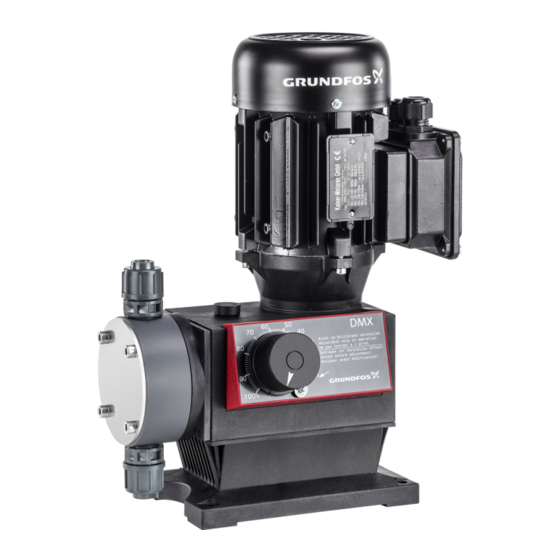
Page 23: Product Introduction
DMX 221 | | 23 5. Product introduction 5.1 Product description 5.1.1 DMX 221 components Pos. Description Motor Gears Eccentric Dosing diaphragm Dosing head Inlet valve Outlet valve Stroke-length adjusting knob AR control unit (optional) Stroke sensor... -
Page 24: Functional Principle Of The Pump
DMX 221 | | 24 5.1.2 Functional principle of the pump DMX pumps are reciprocating displacement pumps with electric motor and a mechanical dia- phragm. • Alternating strokes cause the diaphragm to increase and decrease the size of the dosing chamber and by that draw in and force out dosing medium through the inlet and outlet valves. -
Page 25: Stroke Sensor
5.2.1 Intended use DMX 221 pumps are suitable for dosing liquid, non-flammable and non-combustible media strictly in accordance with these installation and operating instructions. Do not use DMX 221 pumps in potentially explosive environments. DMX dosing pumps can only be operated in a safe and effective way, if they are installed properly and the required ambient conditions are provided. -
Page 26: Identification
DMX 221 | | 26 5.3 Identification 5.3.1 Nameplate Grundfos Water Treatment GmbH - Reetzstr. 85 - D - 76327 Pfinztal DMX 50-10 B-PVC/V/G-X-G1B1B1X 96684204 Type: DMX 221 S/N:00000039 50,00 l/h, 10,00 bar, 50 Hz 0,090 kW, IP65/F 220-400V 50/60Hz... -
Page 27: Type Key
DMX 221 | | 27 5.3.2 Type key Example: DMX 4-10 B-PP/E/T-X-E1B3B3E0 Position Designation Code Description Type range DMX Motor-driven diaphragm dosing pump Flow rate Flow rate [l/h] at maximum counterpressure Pressure Maximum counterpressure [bar] Control variant Standard version with manual control... - Page 28 DMX 221 | | 28 Code Description Servomotor, 1 x 230 V, 50/60 Hz, 1 KΩ potentiometer control Servomotor, 1 x 115 V, 50/60 Hz, 1 KΩ potentiometer control Servomotor, 1 x 24 V, 50/60 Hz, 1 KΩ potentiometer control...
- Page 29 DMX 221 | | 29 Position 9: Supply voltage Code Description 3 x 230/400 V, 50/60 Hz, 460 V, 60 Hz 1 x 230 V, 50/60 Hz (motors ≤ 0.09 kW) 1 x 115 V, 50/60 Hz (motors ≤ 0.09 kW)
- Page 30 DMX 221 | | 30 Code Description Safety plug type F (Schuko), for single-phase motors with AR control unit Plug for the USA and Canada, for single-phase motors with AR control unit Plug for Switzerland, for single-phase motors with AR control unit...
-
Page 31: Taking The Product Out Of Operation
DMX 221 | Taking the product out of operation | 31 6. Taking the product out of operation WARNING Chemical hazard Death or serious personal injury ● Observe the material safety data sheet of the dosing medium. ● Wear protective clothing when working on the dosing head, connections or lines. -
Page 32: Maintaining The Product
DMX 221 | | 32 7. Maintaining the product 7.1 Maintenance schedule Maintenance interval Task Monthly Check that dosing medium is not leaking out of the pump. Monthly Clean the product with a soft cloth and pay spe- cial attention to the fan cover. -
Page 33: Safety Instructions For Maintaining The Dosing Diaphragm Or The Valves
DMX 221 | | 33 7.2 Safety instructions for maintaining the dosing diaphragm or the valves WARNING Chemical hazard Death or serious personal injury ● Observe the material safety data sheet of the dosing medium. ● Wear protective clothing when working on the dosing head, connections or lines. -
Page 34: Cleaning Or Replacing The Inlet And Outlet Valves
DMX 221 | | 34 7.4 Cleaning or replacing the inlet and outlet valves • Observe section Safety instructions for maintaining the dosing diaphragm or the valves • Observe section Preparing for maintenance of the dosing diaphragm or the valves Fig. - Page 35 DMX 221 | | 35 Fig. 7.4-2 Exploded view of inlet and outlet valves DN 20 Pos. Description Spring-loaded as an option. Stainless steel (SS) 1. Unscrew the valve. 2. Disassemble the valve. • DN 8, not spring-loaded: Press out the valve cartridge and remove the valve seat from the ball cage.
-
Page 36: Cleaning Or Replacing The Dosing Diaphragm
DMX 221 | | 36 Related information • 7.3 Preparing for maintenance of the dosing diaphragm or the valves • 7.2 Safety instructions for maintaining the dosing diaphragm or the valves 7.5 Cleaning or replacing the dosing diaphragm • Observe section Safety instructions for maintaining the dosing diaphragm or the valves •... -
Page 37: Returning The Product
● Collect and dispose of all chemicals in a way that is not harmful to persons or the environment. Grundfos can refuse to accept the product for service, if it is not cleaned from chemicals or if the "Safety declaration" is not provided. -
Page 38: Fault Finding The Product
The inlet line is leaking. Check and seal or replace the inlet line. The inlet line is too small or too long. Check with Grundfos specifications and adapt the inlet line to the specifications. The inlet line is clogged. Clean or replace the inlet line. -
Page 39: The Dosing Flow Is Inaccurate
DMX 221 | | 39 8.4 The dosing flow is inaccurate Cause Remedy There is gas in the dosing head. Deaerate the dosing head. There are crystalline deposits in the valves. Clean the valves. The zero point is set incorrectly. -
Page 40: Technical Data
DMX 221 | | 40 9. Technical data 9.1 Ambient conditions Ambient conditions for operation Parameter Value Ambient temperature 0-40 °C Maximum relative air humidity 70 % at 40 °C, 90 % at 35 °C Ambient conditions for storage Parameter... -
Page 41: Dosing Medium
DMX 221 | | 41 9.2 Dosing medium Dosing medium characteristics The dosing medium must have the following basic characteristics: • liquid • non-flammable. For pumps with integral relief valve, the dosing medium must have the following characteristics in addition: •... -
Page 42: Mechanical Data
DMX 221 | | 42 9.3 Mechanical data 9.3.1 Torque values Torque values for the dosing head screws Use a torque wrench with an accuracy of ± 4 % to tighten the screws. Pump type Torque [Nm] DMX 4-10 DMX 7-10... -
Page 43: Housing Materials
DMX 221 | | 43 9.3.2 Housing materials Pump Material Upper part of pump housing PPE + PA, glass-fibre reinforced Lower part of pump housing PP, glass-fibre reinforced Stroke-length adjusting knob AR control unit Material Upper part of AR housing... -
Page 44: Pump Performance
DMX 221 | | 44 9.3.3 Pump performance Dosing flow and maximum counterpressure The values in the table below apply to the following conditions: • maximum counterpressure at the outlet valve. Take the pressure losses along the outlet line to the injection point into account. - Page 45 DMX 221 | | 45 • maximum counterpressure • dosing medium with viscosity and density similar to those of water • flooded suction 0.5 m • fully deaerated dosing head • stroke length 100 % • three-phase 400 V motor.
- Page 46 DMX 221 | | 46 • dosing medium with viscosity and density similar to those of water • fully deaerated dosing head • standard pump version. Parameter Value Dosing flow fluctuation ± 1.5 % within the control range 1:10 Linearity deviation ±...
-
Page 47: Suction Lift
DMX 221 | | 47 9.3.4 Suction lift The suction lift is the height difference between the medium level in the tank and the inlet valve. Suction lift for dosing medium with viscosity similar to that of water The values in the table below apply to the following conditions: •... -
Page 48: Sound Pressure Level
DMX 221 | | 48 The values in the table are in m, they have to be decreased for dosing media with higher density • non-degassing and non-abrasive liquid • stroke length: 100 % • counterpressure: 1.5 to 3 bar •... -
Page 49: Electrical Data
DMX 221 | | 49 9.4 Electrical data Enclosure class • The enclosure class depends on the motor variant selected and is stated on the motor nameplate. • The specified enclosure class can only be ensured if the power supply cable is connected with the same degree of protection. -
Page 50: Dimensions And Weights
DMX 221 | | 50 9.5 Dimensions and weights 9.5.1 Dimensional sketch Pump type [mm] [mm] [mm] [mm] [mm] [mm] [mm] [mm] [mm] 10.5 max. Pump type [mm] [mm] [mm] [mm] [mm] DMX 4-10 G 5/8 DMX 7-10 G 5/8... - Page 51 DMX 221 | | 51 Pump type [mm] [mm] [mm] [mm] [mm] DMX 18-10 G 5/8 DMX 26-10 G 5/8 DMX 39-4 G 1¼ DMX 60-3 G 1¼ DMX 13.7-16 G 5/8 DMX 16-10 G 5/8 DMX 16-12 G 5/8...
-
Page 52: Weights
DMX 221 | | 52 9.5.2 Weights The values in the table below apply to pumps without AR control unit, Servomotor or VFD. Pump type Plastic dosing head Stainless steel dosing head Weight Weight [kg] [kg] DMX 4-10 DMX 7-10... -
Page 53: Dosing Curves
DMX 221 | | 53 9.6 Dosing curves The dosing curves are approximated curves showing the dependency between pump perform- ance, counterpressure and stroke length. The stated values apply to the following conditions: • Newtonian liquid • density similar to that of water •... -
Page 54: Disposing Of The Product
This product or parts of it must be disposed of in an environmentally sound way. 1. Use the public or private waste collection service. 2. If this is not possible, contact the nearest Grundfos company or service workshop. Related information... -
Page 55: Pump Options And Variants
DMX 221 | | 55 11. Pump options and variants 11.1 Diaphragm leakage sensor Pumps prepared for diaphragm leakage sensor have a special dosing head flange with an optical sensor. The sensor contains an infrared transmitter and an infrared receiver. -
Page 56: Function Of The Electronic Unit For Optical Sensor
DMX 221 | | 56 11.1.1 Function of the electronic unit for optical sensor Relay outputs The electronic unit for optical sensor has two relay outputs: • Relay 1 (C1): potential-loaded output, AC mains voltage, 230 V or 115 V, depending on the model C1 can be used to switch off the pump in case of a diaphragm leakage. -
Page 57: Connecting The Diaphragm Leakage Sensor Electrically With The Electronic Unit For Optical Sensor
DMX 221 | | 57 Insert the plug of the diaphragm leakage sensor into socket 1 of the AR control unit. Related information • 11.1.3 Electrical connection 11.1.3.2 Connecting the diaphragm leakage sensor electrically with the electronic unit for optical sensor Observe section Electrical connection. -
Page 58: Interference Suppression Of Inductive Loads
DMX 221 | | 58 ALARM GND / white +5V / yellow OUT / green REL 2 Fig. 11.1.3.2-1 Wiring diagram Pos. Description Power connection Terminals 1, 2, 3: 230 V AC / 115 V AC Contact output 1 Terminals 5, 6, 7: potential-loaded, 230 V AC / 115 V AC... -
Page 59: Checking The Diaphragm Leakage Sensor
The sensor or the electronic unit is defective: • If the sensor is defective, replace it with a new one. • If the electronic unit is defective, call Grundfos service. 4. Dry the sensor carefully. • The electronic unit indicates that a sensor is connected: Screw the sensor into the hole of the dosing head flange (M14 x 1.5). -
Page 60: Maintaining The Diaphragm Leakage Sensor
● Do not work on the electronic device of the diaphragm leakage sensor. 1. Check the diaphragm leakage sensor. 2. If the sensor is defective, replace it with a new one. 3. If the electronic unit is defective, call Grundfos service. The electronic unit is maintenance-free. Related information • 11.1.4 Checking the diaphragm leakage sensor... -
Page 61: Pumps With Vfd
DMX 221 | | 61 113.5 11.2 Pumps with VFD Observe the installation and operating instructions for the pump and the supplier manual "BU 0180" for the VFD on https://www.nord.com. Pay attention to the special VFD parameter settings for DMX. -
Page 62: Connecting The Vfd To The Power Supply
DMX 221 | | 62 11.2.2 Connecting the VFD to the power supply CAUTION Automatic startup Minor or moderate personal injury ● Make sure the pump has been correctly installed and is ready to be started before you switch on the power supply. - Page 63 DMX 221 | | 63 3. Lead the power supply cable through a cable gland. 4. Strip the cable sheath to a length of approx. 3-5 cm and the wires to a length of 7 mm. 5. Connect the wires to the power supply terminals according to the wiring diagrams printed in the VFD.
-
Page 64: Operating Modes
DMX 221 | | 64 11.2.3 Operating modes Read the supplier manual "BU 0180" for the VFD supplied with the product. The selection of the operating mode (manual or analog) can be made via a central control unit. • If analog input 1 (AIN 1) is activated, manual mode is selected. The VFD is operated via the potentiometer. -
Page 65: Special Vfd Parameter Settings For Dmx
DMX 221 | | 65 Read the supplier manual "BU 0180" for the VFD when setting the operating mode for a VFD variants B-E. 11.2.4 Special VFD parameter settings for DMX • Some parameters have been adapted to DMX pumps. These parameters differ from the de- fault settings mentioned in the supplier manual for the VFD. -
Page 66: Technical Data Of Dmx Pumps With Vfd
DMX 221 | | 66 11.2.5 Technical data of DMX pumps with VFD General technical data • Observe the values stated on the nameplates and in the installation and operating instruc- tions. • For technical data, ambient conditions and operating conditions, see section Technical data. - Page 67 DMX 221 | | 67 A.1. Curves DMX 7-10 (60 Hz) Q = 3 bar DMX 4-10 (50 Hz) Q = 3 bar Q [l/h] Q [l/h] 3 bar 10 bar 3 bar 10 bar 10 20 30 40 50 60 70 80 90 100...
- Page 68 DMX 221 | | 68 DMX 9-10 (60 Hz) Q = 3 bar DMX 17-4 (60 Hz) Q = 3 bar Q [l/h] Q [l/h] 3 bar 3 bar 10 bar 4 bar 1.5 bar 10 20 30 40 50 60 70 80 90 100...
- Page 69 DMX 221 | | 69 DMX 14-10 (60 Hz) Q = 3 bar DMX 8-10 (60 Hz) Q = 3 bar Q [l/h] Q [l/h] 3 bar 3 bar 10 bar 10 bar 10 20 30 40 50 60 70 80 90 100...
- Page 70 DMX 221 | | 70 DMX 26-10 (60 Hz) Q = 3 bar DMX 60-3 (60 Hz) Q = 3 bar Q [l/h] Q [l/h] 3 bar 3 bar 10 bar 1.5 bar 10 20 30 40 50 60 70 80 90 100...
- Page 71 DMX 221 | | 71 DMX 16-12 (60 Hz) Q = 3 bar DMX 27-12 (60 Hz) Q = 3 bar Q [l/h] Q [l/h] 3 bar 3 bar 12 bar 12 bar 90 100 90 100 h [%] h [%]...
- Page 72 DMX 221 | | 72 DMX 50-10 (60 Hz) Q = 3 bar DMX 115-3 (60 Hz) Q = 3 bar Q [l/h] Q [l/h] 3 bar 3 bar 1.5 bar 10 bar 10 20 30 40 50 60 70 80 90 100...
- Page 73 DMX 221 | | 73 B.1. Safety declaration • Please copy, fill in and sign this sheet and attach it to the pump returned for service. • Fill in this document using English or German language. Fault description • Please make a circle around the damaged part.
- Page 74 Telefax: +852-27858664 N-1011 Oslo Phone: +47-22 90 47 00 Turkey Canada Hungary Telefax: +47-22 32 21 50 GRUNDFOS POMPA San. ve Tic. Ltd. Sti. GRUNDFOS Canada Inc. GRUNDFOS Hungária Kft. Gebze Organize Sanayi Bölgesi Poland 2941 Brighton Road Park u. 8...
- Page 75 91834765 0317 ECM: 1203452 www.grundfos.com...
Need help?
Do you have a question about the DMX 221 and is the answer not in the manual?
Questions and answers