Grundfos DMX 221 Installation And Operating Instructions Manual
Dosing pump
Hide thumbs
Also See for DMX 221:
- Installation and operating instructions manual (75 pages) ,
- Safety instructions (18 pages) ,
- Instructions manual (17 pages)

Related Manuals for Grundfos DMX 221


Summary of Contents for Grundfos DMX 221
- Page 1 GRUNDFOS INSTRUCTIONS DMX 221 Dosing pump Installation and operating instructions DMX 221 Installation and operating instructions (all available languages) http://net.grundfos.com/qr/i/99558951...
- Page 3 DMX 221 English (GB) Installation and operating instructions ........5 Čeština (CZ)
- Page 4 Appendix B ..........758 DMX 221...
-
Page 5: Table Of Contents
Taking the product out of operation ..22 • AR control unit: http://net.grundfos.com/qr/i/ Maintaining the product... 23 91834764 Maintenance schedule ... . 23 •... -
Page 6: Qualification And Training
1.4 Symbols on the product The symbols and hazard statements below may Information provided directly on the pump must be appear in Grundfos installation and operating observed and maintained in a readable condition at instructions, safety instructions and service all times. - Page 7 • Observe sections Installation tips and Operating Related information conditions. If you have questions, contact your 2.1 Location Grundfos service partner. 2.2.2 Dosing head connections • Design your dosing system with monitoring and control functions to safeguard the entire system. 2.2.2.1 Connecting hoses •...
- Page 8 In order to prevent backflow in the outlet line and to simplify startup, we recommend that you install a non- return valve (13) in the outlet line. 2.1.2.2 Installation of the inlet line When you install the inlet line, observe the following points: •...
-
Page 9: Mechanical Installation
installation with open outflow or with flooded suction, To protect the inlet line against pressure peaks, we siphon effect may occur. To avoid the siphon effect, recommend that you install a properly sized pulsation install a pressure-loading valve (7) in the outlet line damper (4) directly before the inlet valve of the pump. - Page 10 Place the pump horizontally on a wall bracket or a tank. Fix the pump with the four screws. Tighten the screws gently in order not to damage the housing. 2.2.2 Dosing head connections Make sure the valve gasket is placed correctly. Push the hose firmly onto the nipple or nozzle.
-
Page 11: Electrical Connection
Related information 2.3.3 Making electrical connection without mains plug 2.1.1 Installation requirements • Observe section Safety instructions and 2.3 Electrical connection requirements for electrical connection. Switch off the power supply. 2.3.1 Safety instructions and requirements for electrical connection Open the terminal box on the motor. DANGER Connect the motor according to the wiring Electric shock... -
Page 12: Safety Instructions And Requirements For Startup
3.2 Safety instructions and requirements for startup WARNING Chemical hazard Death or serious personal injury ‐ Observe the material safety data sheet of the dosing medium. ‐ Wear protective clothing when working on the dosing head, connections or lines. ‐ Collect and dispose of all chemicals in a way that is not harmful to persons or the environment. -
Page 13: Stopping And Starting Dosing
The pump is now started up. Make the required For pumps with AR control unit: Press the start/ operating settings. stop button and keep pressing it for continuous operation during the deaeration process. Related information Set the stroke-length adjusting knob to 100 %. 3.1 Preparing the pump for startup Let the pump run until the dosing medium is free 3.1 Preparing the pump for startup... -
Page 14: Adjusting The Dosing Flow Via The Stroke Length
Related information the inlet valve, or use the scaled pulsation 3.2 Safety instructions and requirements for startup damper, if installed on the inlet side. 5.1.1 DMX 221 components For pumps with level control unit, deactivate the 5.1.2 Functional principle of the pump function. -
Page 15: Setting The Opening Pressure Of The Integral Relief Valve
AR control unit, Servomotor or VFD Death or serious personal injury in addition to the instructions in this manual. ‐ Do not set the opening pressure higher • AR control unit: http://net.grundfos.com/qr/i/ than the maximum counterpressure of 91834764 the pump. • Servomotor: http://net.grundfos.com/qr/i/ ‐... -
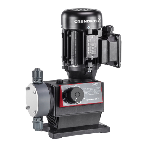
Page 16: Product Introduction
5. Product introduction 5.1 Product description 5.1.1 DMX 221 components Pos. Description Motor Gears Eccentric Dosing diaphragm Dosing head Inlet valve... - Page 17 Related information chamber and by that draw in and force out dosing medium through the inlet and outlet • http://net.grundfos.com/qr/i/91834764 valves. 5.1.4 Functional principle of the integral relief • The dosing strokes are generated by an...
-
Page 18: Applications
5.3.1 Nameplate the required ambient conditions are provided. Observe sections Location and Technical data. Incorrect use Grundfos Water Treatment GmbH - Reetzstr. 85 - D - 76327 Pfinztal • The operational safety of the pump is only XXX XX-XX X-XXX/X/X-X-XXXXXXXXXXX... - Page 19 Control variant DMX 50-10 B-PVC/V/C-X-E1U2U2XEMNG Standard (manual control) Stroke sensor PNP AR control unit, pump mounted AR control unit, wall mounted Servomotor, 1AC 115-230 V, 50/60 Hz, 4-20 mA control (without manual operation) Servomotor, 24 VDC, 4-20 mA control (without manual operation) Dosing head variant DMX 50-10 B-PVC/V/C-X-E1U2U2XEMNG Polypropylene...
- Page 20 Terminal box position (also AR control or VFD position) DMX 50-10 B-PVC/V/C-X-E1U2U2XEMNG Opposite side of dosing head (3 o'clock) Towards dosing head (9 o'clock) Towards adjusting knob (6 o'clock) Supply voltage DMX 50-10 B-PVC/V/C-X-E1U2U2XEMNG 3AC 230/400 V, 50/60 Hz, 440-480 V, 60 Hz (motors < 0.75 kW) 1AC 230 V, 50/60 Hz (motors ≤...
- Page 21 Hydraulic connections (first = outlet, second = inlet) DMX 50-10 B-PVC/V/C-X-E1U2U2XEMNG G 5/8, for hoses 4/6 mm, 6/9 mm, 6/12 mm, 9/12 mm (PVC, PP, PVDF) G 5/8, for pipes with internal thread Rp 1/4 (SS) G 5/8, installation set, including 2 pump connections, foot valve, injection unit, 6 m I007 PVC outlet hose (6/12 mm), 2 m PVC inlet hose (6/12 mm) G 5/4, for hoses with internal diameter 19 or 20 mm and for pipes with external...
-
Page 22: Taking The Product Out Of Operation
Pump design DMX 50-10 B-PVC/V/C-X-E1U2U2XEMNG Grundfos Neutral Related information 2.1.1 Installation requirements 5.1.4 Functional principle of the integral relief valve 10.1 Disposing of hazardous or toxic materials 11.2.1 Identification of pumps with VFD 6. Taking the product out of operation Close the isolating valves on the inlet side and outlet side, if installed. -
Page 23: Maintaining The Product
Send the 7.6 Cleaning or replacing the diaphragm of the pump to integral relief valve Grundfos or an authorised 7.3 Preparing for maintenance of the dosing service diaphragm or the valves workshop. Only adjust the stroke length while the... -
Page 24: Cleaning Or Replacing The Inlet And Outlet Valves
Close the vent plug when taking the pump out of operation for transport, storage or service. Flush the dosing head with water, if possible. While the pump is running, set the stroke-length adjusting knob to 100 %. Switch off the pump and disconnect it from the power supply. -
Page 25: Cleaning Or Replacing The Dosing Diaphragm
The O-rings must be correctly placed in the specified grooves. Re-assemble the valve. Refit the valve in correct orientation. The direction arrow on the valve must point in the flow direction (upwards). Related information 7.1 Maintenance schedule 7.2 Safety instructions for maintaining the dosing diaphragm or the valves 7.3 Preparing for maintenance of the dosing diaphragm or the valves... -
Page 26: Cleaning Or Replacing The Diaphragm Of The Integral Relief Valve
7.6 Cleaning or replacing the diaphragm of the environment. the integral relief valve Grundfos can refuse to accept the product for service, • Observe section Safety instructions for if it is not cleaned from chemicals or if the "Safety maintaining the dosing diaphragm or the valves declaration"... -
Page 27: The Dosing Pump Does Not Suck In
Wait until the pump has leaking. the inlet line. line and the dosing deaerated. head. Check with Grundfos The inlet line is too specifications and adapt The stroke-length Turn the stroke-length small or too long. the inlet line to the adjusting knob is set to adjusting knob. -
Page 28: Permanent Leakage From The Integral Relief Valve
The AR control unit or The dosing diaphragm is Replace the dosing the electronic unit for Contact Grundfos for worn (incipient rips). diaphragm. optical sensor does not service. operate properly. The dosing pump is used... -
Page 29: Mechanical Data
9.3 Mechanical data Medium temperature for pumps with PVC dosing head 9.3.1 Torque values Medium Maximum counterpressure Torque values for the dosing head screws temperature Use a torque wrench with an accuracy of ± 4 % to Up to 12 bar 0-40 °C tighten the screws. - Page 30 Related information Max. Max. dosing capacity counterpressure 3.5 Deaerating the pump during operation Pump 7.5 Cleaning or replacing the dosing diaphragm 50 Hz 60 Hz type 7.6 Cleaning or replacing the diaphragm of the [bar] [psi] [l/h [l/h] US [gph] integral relief valve 9.3.2 Housing materials 4-10 Pump...
- Page 31 Max. Stroke Max. dosing capacity Maximum stroke rate counterpressure volume Pump Pump type 50 Hz 60 Hz 50 Hz 60 Hz type [bar] [psi] [l/h [n/min] [n/min] [l/h] US [gph] DMX 18-10 15.8 DMX 25-3 50-10 DMX 26-10 19.0 60-3 DMX 27-10 DMX 27-12 23.8...
- Page 32 Suction lift for dosing medium with viscosity Suction lift for dosing medium with maximum similar to that of water viscosity The values in the table below apply to the following The values in the table below apply to the following conditions: conditions: •...
-
Page 33: Electrical Data
9.4 Electrical data Max. suction Max. lift with max. Pump type Enclosure class viscosity [mPas] viscosity [m] • The enclosure class depends on the motor variant selected and is stated on the motor DMX 50-10 1 nameplate. DMX 60-3 • The specified enclosure class can only be ensured if the power supply cable is connected DMX 75-4... -
Page 34: Dimensions And Weights
9.5 Dimensions and weights 9.5.1 Dimensions DMX 221 All dimensions are in mm, except for the thread designations. Pump type 102.5 10.5 Pump type DMX 4-10 / DMX 7-10 / DMX 7,2-16 / DMX 8-10 / DMX 9-10 / DMX 12-10 / DMX... -
Page 35: Dosing Curves
11.2.5.1 Dimensional sketch of DMX pumps with • standard pump version. 9.5.2 Weights DMX 221 Abbreviation Description The values in the table below apply to pumps without AR control unit, Servomotor or VFD. Dosing flow Zero point of the pump. -
Page 36: Disposing Of The Product
Observe the installation and operating instructions for the AR control unit. Use the public or private waste collection service. If this is not possible, contact the nearest Grundfos company or service workshop. Related information 1. General information The crossed-out wheelie bin symbol 3.11 Operating the pump with electronics... - Page 37 Remove the cover with the plastic screws from 11.1.3.2 Connecting the diaphragm leakage the electronic unit. sensor electrically with the electronic unit for optical sensor Mount the electronic unit on the wall by means of Observe section Electrical connection. the four screws. If the diaphragm leakage sensor is used with an Tighten the screws gently in order not to damage electronic unit for optical sensor, the diaphragm...
-
Page 38: Diaphragm Leakage Sensor
- If the sensor is defective, replace it with a sensor will damage relays and contactors. new one. • Inductive loads on the electronic unit can be - If the electronic unit is defective, call eliminated by means of a suppressor circuit as Grundfos service. the one described below. -
Page 39: Pumps With Vfd
11.1.2 Mounting the electronic unit for optical sensor If the sensor is defective, replace it with a new one. 11.2 Pumps with VFD If the electronic unit is defective, call Grundfos Observe the installation and operating service. instructions for the pump and the supplier The electronic unit is maintenance-free. - Page 40 11.2.1 Identification of pumps with VFD Pumps with motors with PTC sensor and VFD are available in different variants which are shown on the nameplate and explained in the type key. The last two L3 L2/N L1 PE letters of the type designation indicate the VFD variant.
- Page 41 Refit the front cover of the VFD power unit and tighten the screws. Tighten the screws with 3.5 Nm ± 20 %. Related information 3.1 Preparing the pump for startup 11.2.5 Technical data of DMX pumps with VFD 11.2.3 Operating modes Read the supplier manual "BU 0180" for the VFD supplied with the product.
- Page 42 Control terminals Modifications of other parameters and adaptation of the inputs and outputs can be made by means of the Code Index Parameter Value for DMX optional "parameter box" or the "NordCon" software. Read the supplier manual "BU 0180" for the VFD Setpoint input provided with the product.
- Page 43 11.2.5.1 Dimensional sketch of DMX pumps with VFD For all other dimensions, see section "Dimensional sketch". Pump type [mm] [mm] [mm] [mm] Related information 9.5.1 Dimensions DMX 221...
- Page 44 Appendix A A.1. Curves DMX 7-10 (60 Hz) Q = 3 bar DMX 4-10 (50 Hz) Q = 3 bar Q [l/h] Q [l/h] 3 bar 10 bar 3 bar 10 bar 10 20 30 40 50 60 70 80 90 100 h [%] 10 20 30 40 50 60 70 80 90 100 h [%]...
- Page 45 DMX 8-10 (50 Hz) Q = 3 bar DMX 9-10 (60 Hz) Q = 3 bar Q [l/h] Q [l/h] 3 bar 3 bar 10 bar 10 bar 10 20 30 40 50 60 70 80 90 100 10 20 30 40 50 60 70 80 90 100 h [%] h [%] DMX 12-10 (50 Hz) Q...
- Page 46 DMX 14-10 (60 Hz) Q = 3 bar DMX 13,7-16 (50 Hz) Q = 3 bar Q [l/h] Q [l/h] 3 bar 3 bar 16 bar 10 bar 10 20 30 40 50 60 70 80 90 100 10 20 30 40 50 60 70 80 90 100 h [%] h [%] DMX 16-10 (50 Hz) Q...
- Page 47 DMX 17-4 (60 Hz) Q = 3 bar DMX 16-12 (50 Hz) Q = 3 bar Q [l/h] Q [l/h] 3 bar 3 bar 4 bar 12 bar 1.5 bar 90 100 10 20 30 40 50 60 70 80 90 100 h [%] h [%] DMX 18-10 (50 Hz) Q...
- Page 48 DMX 25-3 (50 Hz) Q = 3 bar DMX 26-10 (60 Hz) Q = 3 bar Q [l/h] Q [l/h] 3 bar 3 bar 1.5 bar 10 bar 10 20 30 40 50 60 70 80 90 100 10 20 30 40 50 60 70 80 90 100 h [%] h [%] DMX 25-3 (60 Hz) Q...
- Page 49 DMX 35-10 (60 Hz) Q = 4 bar DMX 27-12 (50 Hz) Q = 3 bar Q [l/h] Q [l/h] 4 bar 3 bar 10 bar 12 bar 90 100 10 20 30 40 50 60 70 80 90 100 h [%] h [%] DMX 39-4 (50 Hz) Q...
- Page 50 DMX 50-10 (50 Hz) Q = 3 bar DMX 60-3 (60 Hz) Q = 3 bar Q [l/h] Q [l/h] 3 bar 3 bar 10 bar 1.5 bar 10 20 30 40 50 60 70 80 90 100 10 20 30 40 50 60 70 80 90 100 h [%] h [%] DMX 50-10 (60 Hz) Q...
- Page 51 DMX 115-3 (50 Hz) Q = 3 bar Q [l/h] 3 bar 1.5 bar 10 20 30 40 50 60 70 80 90 100 h [%] DMX 115-3 (60 Hz) Q = 3 bar Q [l/h] 3 bar 1.5 bar 10 20 30 40 50 60 70 80 90 100 h [%] Related information...
- Page 52 Appendix B B.1. Safety declaration • Please copy, fill in and sign this sheet and attach it to the pump returned for service. • Fill in this document using English or German language. Fault description • Please make a circle around the damaged part. •...
- Page 53 Argentina China Germany Bombas GRUNDFOS de Argentina S.A. GRUNDFOS Pumps (Shanghai) Co. Ltd. GRUNDFOS GMBH Ruta Panamericana km. 37.500 Centro 10F The Hub, No. 33 Suhong Road Schlüterstr. 33 Industrial Garin Minhang District 40699 Erkrath 1619 - Garín Pcia. de B.A.
- Page 54 Fax: +66-2-725 8998 LT-03201 Vilnius Москва, RU-109544, Russia Turkey Tel.: + 370 52 395 430 Тел. (+7) 495 564-88-00 (495) 737-30-00 GRUNDFOS POMPA San. ve Tic. Ltd. Fax: + 370 52 395 431 Факс (+7) 495 564 8811 Sti. E-mail grundfos.moscow@grundfos.com Malaysia Gebze Organize Sanayi Bölgesi...
- Page 55 99558951 0919 ECM: 1250494...
Need help?
Do you have a question about the DMX 221 and is the answer not in the manual?
Questions and answers